86 Chapter 6 Use Of Monitoring Module M501D
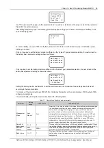
1: 2043040501
54.1V 30.2A
AC: On DC: On
AC: 220V
CurrLimit: 34%
AC Derated: Y
Temp Derated: N
1: 2043040501
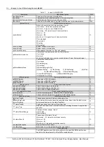
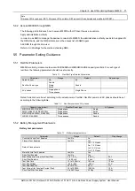
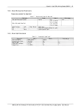
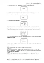
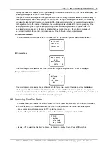
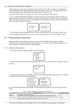
The information of every rectifier is displayed in two pages. The information in the first screen includes: the last 10
digits of the serial number of the corresponding module, the output voltage, output current, the AC/DC switch status,
the AC input voltage. The information in the second screen includes: the last 10 digits of the serial number of the
corresponding module, the current limiting threshold, the AC power derated status, the temperature derated status.
Press ► to scroll to the next page, or ◄ to return to the last.
4. Press▼ or ▲ to view other rectifiers’ information.
The information of 48 modules can be displayed at most. If the module does not exist, no information will be
displayed. If the communication of the module is interrupted, the information will be highlighted.
5. At any rectifier information page, press ESC repeatedly and you can return to the higher-level menus.
6.5 Querying And Handling Alarms
The monitoring module can locate and record the system fault according to the collected data, generate audio and
video alarm and dry contact output according to the set alarm level, and report the alarm to the MC. Meanwhile, the
user can query the alarm history record and active alarm record on the LCD of the monitoring module.
6.5.1 Querying Active Alarm
When a new alarm is raised, if there is no key pressing operation on the monitoring module, two minutes later, the
monitoring module will automatically pop up the active alarm screen on the LCD.
If there exist multiple alarms in the system, the viewing steps are as follows:
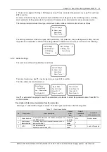
1. At any system information page, press ENT to enter the main menu.
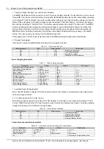
2. Use ▲ or ▼ to select the ‘Status’ submenu in the main menu and press ENT to confirm.
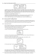
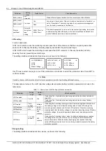
STATUS
Rectifiers
Active Alarm
Alarm History
3. Use the ▲ or ▼ key to select the ‘active alarm’ submenu in the submenu screen, and press the ENT screen to
confirm and run the active alarm information screen.
Press ▲ or ▼ to select the ‘Active Alarm’, as shown in the above figure, and press ENT to confirm.
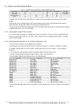
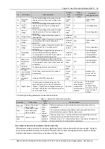
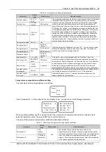
1) If there is no active alarm, ‘Active Alarm None’ will be displayed
Active Alarm
NONE
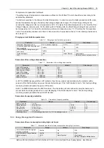
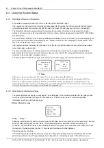
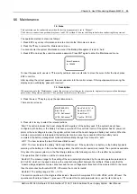
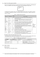
2) If there is active alarm, the screen will display the following information:
Active Alarm
100
1 Alarm
SPD Fault
040501 02:40:20
040501 19:56:04
On the active alarm information menu, the display contents include; the alarm sequence number, alarm level, alarm
name and time (year, month, day, hour, minute, and second). The display sequence will follow the sequence of the
occurring time of the alarms. The latest alarm will be displayed as the first one. Use ▲ or ▼ to view all active alarms.
NetSure 501 A50, NetSure 501 AA0, NetSure 701 A51 19-Inch Subrack Power Supply System User Manual

