background image

4

GENERAL MAINTENANCE

We recommend that all Keystone PCS17 knife 
gates be inspected at least every 60 days.
The following points should be examined and 
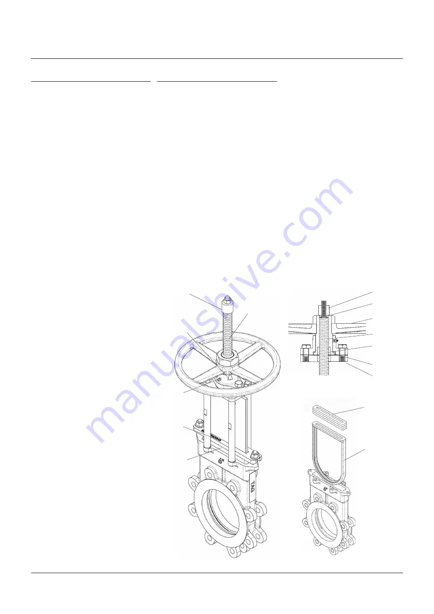
corrected as required (Figure 4):
1.  Exterior overview: As piping system 

components are subject to certain levels of 
erosion and corrosion, periodic inspections 
should be made as valves/components 
may wear over time. Regular inspection 
of the valve body and gate should be 
performed, check for general signs of 
corrosion, component wear and/or damage 
caused by process media, i.e. wire draw, 
steam cutting. If possible, check body wall 
and gate thicknesses using calibrated 
measuring devices such as micrometers 
and/or ultrasonic thickness gauges. 
Severe applications may require additional 
inspection types and/or frequency.

2.  Valve spindles, extension spindles, and 

spindle nut: Look for excessive corrosion, 
galling or lack of lubrication. If valve 
spindle requires lubrication, utilize the 
grease fitting provided and pump standard 
bearing grease through the yoke hub 
to lubricate the spindle and spindle nut 
assembly. Additional lubrication may be 
applied directly onto spindle or spindle 
threads. (Use material which meets 
ASTM 4950 GBLB.)

3.  Stop nut adjustment (manual valves): 

Check tightness of stop nut on valve spindle

4.  Packing gland: Check for leaks or worn 

packing. If leakage is occurring around the 
packing gland, tighten the packing gland 
bolts, being careful not to overstress the 
bolting. If the valve requires repacking, 
you may use any standard square braided 
packing as suitable for your service. 
See additional instructions for repacking 
on page 5.

5.  If possible stroke the valve through the full 

open and closed position to make sure it is 
functioning properly.

KEYSTONE

 FIGURE PCS17 KNIFE GATE VALVES

INSTRUCTION, OPERATION AND MAINTENANCE MANUAL

NOTES

1.  Stop all small packing or seat leaks as soon as 

possible as considerable damage can be done 
to the valve and the surrounding area if leakage 
is allowed to continue to grow.

2.  Replacement parts including handwheel and yoke 

assemblies, gates, packing glands, seats and 
packing can be provided from our factory.

SPARE PARTS

The following spare parts are recommended:

Cylinder operator (if applicable)

1 - Repair kit

Valves

1 - Replacement seat (Figure 6)
1 - Replacement packing set.
1.  When ordering replacement parts for a 

Keystone product or cylinder operator, 
please include valve or cylinder size 
and complete description including 
serial number with your request.

2.  Additional replacement parts such as 

handwheels, spindle nut assemblies, 
retainers, yoke posts, spindles, packing 
glands, and gates are available from factory. 
Again, please provide complete description 
with serial number when ordering.

Seat

FIGURE 6

FIGURE 5

Stop nut

Spindle 

assembly

Retaining nut

Handwheel

Spindle nut

Retainer

Retainer bolt

Packing

Stop nut

Spindle nut

(under retainer)

Spindle

Grease fitting

Packing gland

Packing

FIGURE 4

Summary of Contents for KEYSTONE FIGURE PCS17

Page 1: ...0 is per MSS SP44 with the face to face per MSS SP81 The bolt holes in the chest or upper flange area are blind tapped see Figure 2 2017 Emerson All Rights Reserved Emerson com FinalControl VCIOM 02874 EN 19 05 NOTES 1 All knife gate valves are designed and manufactured to be installed in applications where no more than 1g 0 04 oz of force In excess of gravity is applied to the valve in any direct...

Page 2: ...el may be too hot to handle take reasonable preCautions Severe temperature applications may require optional insulation the valves to protect operators from the heat TABLE A MAX FLANGE BOLT TORQUE Bolt size Torque Imperial Metric lb ft Nm NOTE Body can be deformed or fractured if flange bolting is too long or overtorqued KEYSTONE FIGURE PCS17 KNIFE GATE VALVES INSTRUCTION OPERATION AND MAINTENANCE...

Page 3: ... 21 25 4 1 8 412 75 16 25 76 2 3 533 4 21 TBL D 470 12 525 M24 438 76 2 533 4 TBL E 470 12 525 M24 438 76 2 533 4 400 16 SP 81 539 75 21 25 16 596 9 23 5 25 4 1 8 469 9 18 5 88 9 3 5 596 9 23 5 TBL D 521 12 580 M24 489 88 9 596 9 TBL E 521 12 580 M24 489 88 9 596 9 450 18 SP 81 577 85 22 75 16 635 25 28 575 1 7 533 4 21 88 9 3 5 641 4 25 25 TBL D 584 12 640 M24 532 88 9 641 4 TBL E 584 16 640 M24 ...

Page 4: ...cking gland tighten the packing gland bolts being careful not to overstress the bolting If the valve requires repacking you may use any standard square braided packing as suitable for your service See additional instructions for repacking on page 5 5 If possible stroke the valve through the full open and closed position to make sure it is functioning properly KEYSTONE FIGURE PCS17 KNIFE GATE VALVE...

Page 5: ...cking all around the gate one row at a time 2 Tamp packing into packing box even and flat using flat bar or other suitable tool 3 Add next row alternating sides of the gate where the ends of the packing meet against each other Ends of packing must not line up If they do premature leakage could occur Complete by adding the number of rows required Figure 8 Prepare valve 1 Relieve pressure on valve o...

Page 6: ...ate from valve lifter by removing gate bolts 6 Remove top plate hex nuts and washers from four post yoke 7 Pull entire actuator assembly up and away from valve set aside 8 Pull gate from valve body examine gate for flatness and damage replace if necessary 9 Thoroughly remove old packing 10 Remove seat Note to remove seat it will be necessary to slip a pry tool through the gate slot in the packing ...

Page 7: ...bar Seat should be firmly seated inseat channel at this time 5 Insert gate into packing box radiused end first pushing it straight down through the packing support bar and into valve throat as far as possible by hand Figure 12 6 Repack valve see Page 5 for instructions do not fully tighten 7 Reassemble actuator assembly aligning top plate with four post yoke and aligning gate bolt holes with valve...

Page 8: ...UNTING Cylinders require additional support when mounted in the other than vertical position Failure to do so could lead to premature failure of cylinder and or valve The following illustrations are suggestions specific details will have to be determined by customer so support best suits surrounding area It is important that the cylinder gate alignment be maintained during valve operation Supports...

Page 9: ...be shipped with the thrust spindle nut installed in the bevel gear 2 Place the adapter plate over the 4 Post yoke legs aligning the holes Figure 14 3 Attach nuts onto 4 post yoke legs securing the top plate into position 4 Apply standard bearing grease onto to exposed spindle thread Use material which meets ASTM 4950 GBLB 5 Slip the bevel gear over the spindle nut engaging the threads Rotate the h...

Page 10: ...ockout options are available on all valves The following are the factory s recommendations for storage procedures to retain maximum product integrity during long term storage of 1 to 5 years The shelf life listed is a guideline and is not a substitute for examination of cured material at the time of intended use To maintain shelf life spare seats should be stored in accordance with the following 1...

Page 11: ...B Preparation for storage Valves may be stored as shipped provided the above storage facility and equipment orientation instructions above are followed If valve packaging is altered or removed for receiving inspection repackage valve as originally received C Cylinder storage These cylinder storage instructions are not intended to replace the instructions of the specific cylinder manufacturer and a...

Page 12: ...son logo are trademarks and service marks of Emerson Electric Co All other marks are the property of their respective owners The contents of this publication are presented for informational purposes only and while every effort has been made to ensure their accuracy they are not to be construed as warranties or guarantees express or implied regarding the products or services described herein or the...

Reviews: