


94
Digitax ST User Guide
Issue: 5
Table 9-103 Homing acceleration
9.23 Cyclic sync position mode
Cyclic sync position mode is supported in servo mode.
Table 9-104 Cyclic sync position mode
When using one of the DSP-402 positioning modes, Distributed Clocks
must be enabled. Failure to do so may result in the EtherCAT interface
going into the SAFE-OPERATIONAL state (Pr
17.04
= 4).
Cyclic sync position mode provides linear interpolation which will always
insert a delay of one position command. The time specified must always
be an integer multiple of the control loop cycle time. The time period
index has a minimum value of -6 (i.e. the smallest time unit will be
microseconds). The time period is checked to ensure that it an integer
multiple of the control loop cycle time.
A velocity feed forward will be calculated for the position controller. On
each interpolator time period, a value is read from the target_position
object. The correct number of data points for linear interpolation is stored
internally. When a new target position is loaded in, the oldest position
command in the data set will be discarded.
9.23.1 0x6077 Torque_actual_value
This object provides the actual value of the torque. It shall correspond to
the instantaneous torque in the motor. The value is given per thousand
of rated torque.
Table 9-105 Torque actual value
9.23.2 0x607A Target_position
This object indicates the commanded position that the drive should
move to in cyclic sync position mode using the current settings of motion
control parameters such as velocity, acceleration, deceleration, motion
profile type etc. The value of this object is given in user-defined position
units.
Table 9-106 Target position
9.23.3 0x60B1 Velocity offset
This object provides the offset for the velocity value. The offset is given
in user defined velocity units. In cyclic synchronous position mode this
object contains the input value for velocity feed forward.
Table 9-107 Velocity offset
9.24 Advanced features
9.24.1 Distributed Clocks
The EtherCAT interface supports Distributed Clocks. This is the scheme
used by EtherCAT to accurately time synchronize slave devices.
Position, speed and current control loops can all be synchronized.
When the EtherCAT interface is connected to a drive which can take a
time synchronization signal, the EtherCAT Distributed Clocks facility can
be used to provide this signal so the drive speed and current tasks are
synchronized to the network. The position controller, and appropriate
motion features will also be synchronized to the drive speed task.
In CoE interpolated position mode the position command provided by
the master every interpolation cycle time is used to generate a position
command for the drive every 250 µs.
9.24.2 Time synchronization support
When the EtherCAT interface is connected to a drive which can take a
time synchronization signal, the EtherCAT Distributed Clocks facility can
be used to provide this signal so the drive speed and current tasks are
synchronized to the network. The position controller, and appropriate
motion features will also be synchronized to the drive speed task.
The time between edges of the drive synchronization square wave
(referred to as the drive synchronization interval) will be an integer
multiple of 250 µs (up to a maximum value of 15 ms).
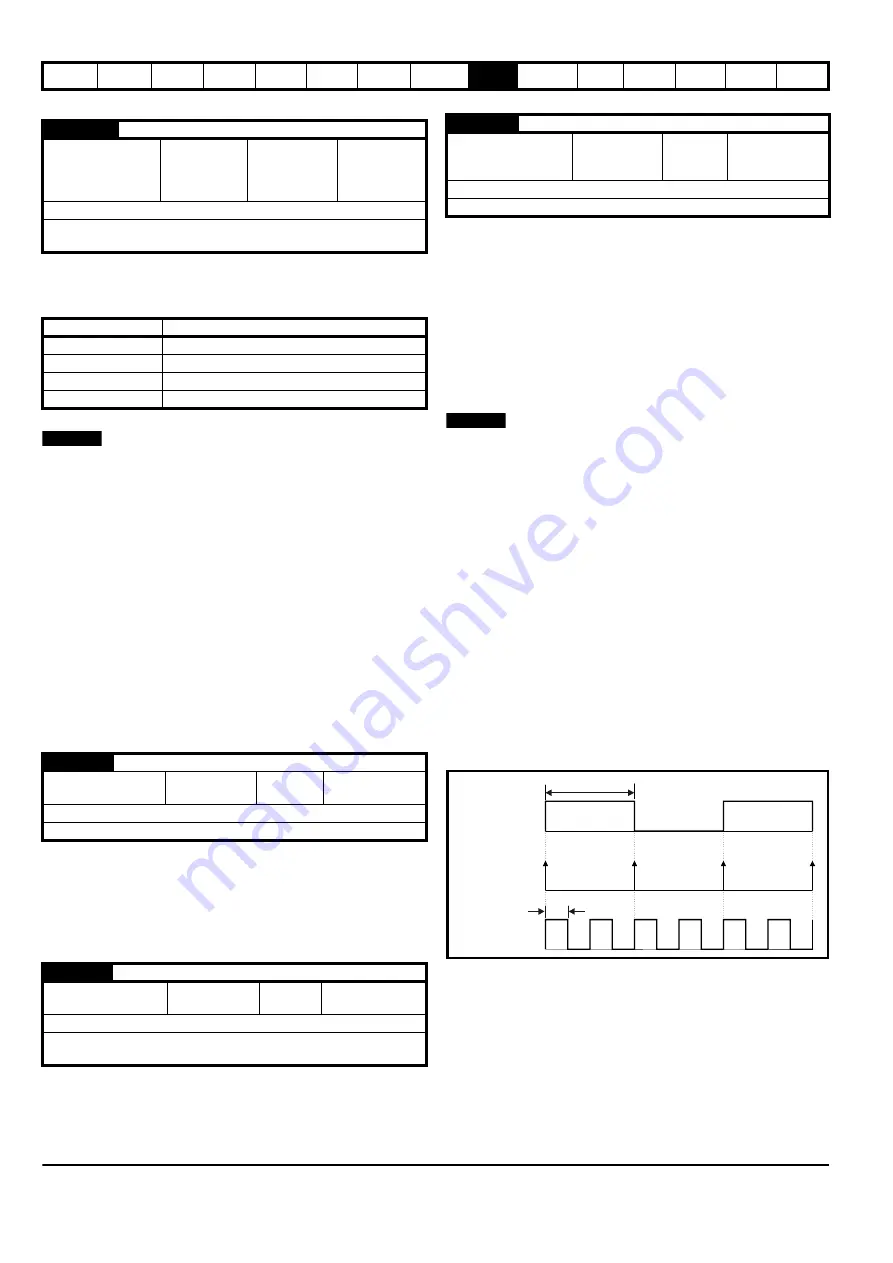
The position controller will be executed at the interval defined in the
Distributed Clock settings, if Distributed Clocks is disabled the controller
will execute each 250 µs. When the profile torque or velocity control
mode is used with Distributed Clocks enabled, a new profile cycle will be
started every sync interval in the control loop cycle starting at the sync
signal edge as shown in Figure 9-20. This will be referred to as a profile
cycle. When Distributed Clocks are not enabled, a new profile cycle will
be started every 250 µs.
Figure 9-20 Profile Cycle Timing
0x609A
Homing acceleration
Access: RW
Range: 0 to
0xFFFFFFFF
Size: Unsigned
32
Unit: User-
defined
acceleration
units
Default: 0
Description:
Indicates the configured acceleration and deceleration to
be used during homing operation.
Index
Name
0x6077
torque_actual_value
0x607A
target_position
0x60B1
velocity_offset
0x60C2
interpolation_time_period
0x6077
Torque actual value
Access: RO
Range: -32768
to +32767
Size:
Signed 16
Unit: 0.1% of
rated torque
Default:
0
Description: Provides the actual value of the torque.
0x607A
Target position
Access:
RW
Range: 0 to
0xFFFFFFFF
Size:
Signed 32
Unit: User-defined
position units
Default:
N/A
Description:
Indicates the command positions that the drive should
move to in cyclic sync position mode.
NOTE
0x60B1
Velocity offset
Access: RW
Range: 0 to
0xFFFFFFFF
Size:
Signed 32
Unit: User-
defined velocity
units
Default: 0
Description: Provides the offset for the velocity value.
NOTE
Interrupt 1 cycle time
500
μ
s
Drive synchronization
waveform
Control loop cycles
Profile cycles
Summary of Contents for Digitax ST
Page 1: ...User Guide AC variable speed drive for servo motors Part Number 0475 0001 05 Issue 5 ...
Page 209: ......
Page 210: ...0475 0001 05 ...


