


56
Digitax ST User Guide
Issue: 5
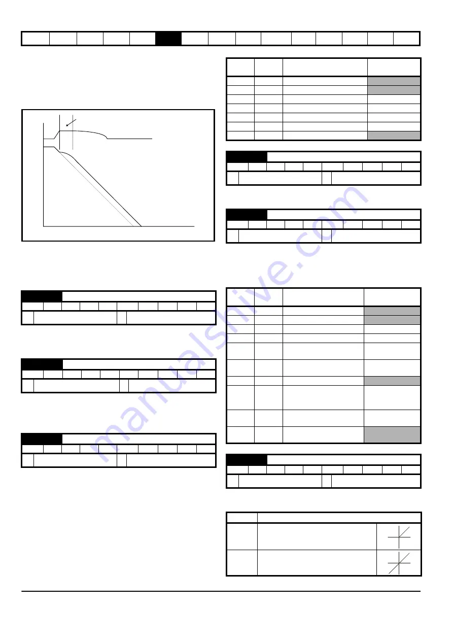
reaches the programmed deceleration rate the controller ceases to
operate and the drive continues to decelerate at the programmed rate. If
the standard ramp voltage (Pr
2.08
) is set lower than the nominal DC bus
level the drive will not decelerate the motor, but it will coast to rest. The
output of the ramp controller (when active) is a current demand that is fed
to the torque producing current controller (Servo mode). The gain of these
controllers can be modified with Pr
4.13
and Pr
4.14
.
2: Standard ramp with motor voltage boost
This mode is the same as normal standard ramp mode except that the
motor voltage is boosted by 20 %. This increases the losses in the
motor, dissipating some of the mechanical energy as heat giving faster
deceleration.
Setting Pr
0.16
to 0 allows the user to disable the ramps. This is
generally used when the drive is required to closely follow a speed
reference which already contains acceleration and deceleration ramps.
A first order filter, with a filter defined by Pr
0.17
, is provided on the
current demand to reduce acoustic noise and vibration produced as a
result of position feedback quantization noise. The filter introduces a lag
in the speed loop, and so the speed loop gains may need to be reduced
to maintain stability as the filter is increased.
In modes 2 & 3 a current loop loss trip is generated if the current falls
below 3 mA.
In modes 2 & 4 the analog input level goes to 0.0 % if the input current
falls below 4 mA.
Pr
0.20
sets the destination of analog input 2.
In modes 2 & 3 a current loop loss trip is generated if the current falls
below 3 mA.
In modes 2 & 4 the analog input level goes to 0.0 % if the input current
falls below 4 mA.
Pr
0.22
determines whether the reference is uni-polar or bi-polar as
follows:
0.16 {2.02}
Ramp enable
RW
Bit
US
Ú
OFF (0) or On (1)
Ö
On (1)
0.17 {4.12}
Current demand filter
RW
Uni
US
Ú
0.0 to 25.0 ms
Ö
0.0
0.19 {7.11}
Analog input 2 mode
RW
Txt
US
Ú
0 to 6
Ö
VOLt (6)
DC bus voltage
Motor Speed
Programmed
deceleration
rate
t
Controller
operational
Pr
value
Pr
string
Mode
Comments
0
0-20
0 - 20 mA
1
20-0
20 - 0 mA
2
4-20.tr
4 - 20 mA with trip on loss
Trip if I < 3 mA
3
20-4.tr
20 - 4 mA with trip on loss
Trip if I < 3 mA
4
4-20
4 - 20 mA with no trip on loss
0.0 % if I
≤
4 mA
5
20-4
20 – 4 mA with no trip on loss 100 % if I
≤
4 mA
6
VOLt
Voltage mode
0.20 {7.14}
Analog input 2 destination
RW
Uni
DE
PT
US
Ú
Pr
0.00
to Pr
21.51
Ö
Pr
1.37
0.21 {7.15}
Analog input 3 mode
RW
Txt
PT
US
Ú
0 to 9
Ö
th (8)
Pr
value
Pr
string
Mode
Comments
0
0-20
0 - 20 mA
1
20-0
20 - 0 mA
2
4-20.tr
4 - 20 mA with trip on loss
Trip if I < 3 mA
3
20-4.tr
20 - 4 mA with trip on loss
Trip if I < 3 mA
4
4-20
4 - 20 mA with no trip on
loss
0.0% if I
≤
4 mA
5
20-4
20 - 4 mA with no trip on
loss
100 % if I
≤
4 mA
6
VOLt
Voltage mode
7
th.SC
Thermistor mode with short-
circuit detection
Th trip if R > 3K3
Th reset if R < 1K8
ThS trip if R < 50R
8
th
Thermistor mode with no
short-circuit detection
Th trip if R > 3K3
Th reset if R < 1K8
9
th.diSp
Thermistor mode with
display only and no trip
0.22 {1.10}
Bipolar reference select
RW
Bit
US
Ú
OFF (0) or On (1)
Ö
OFF (0)
Pr 0.22
Function
0
Unipolar speed/reference
1
Bipolar speed/reference
Summary of Contents for Digitax ST
Page 1: ...User Guide AC variable speed drive for servo motors Part Number 0475 0001 05 Issue 5 ...
Page 209: ......
Page 210: ...0475 0001 05 ...


