background image

ControlWave Instruction Manual (CI-ControlWave) 


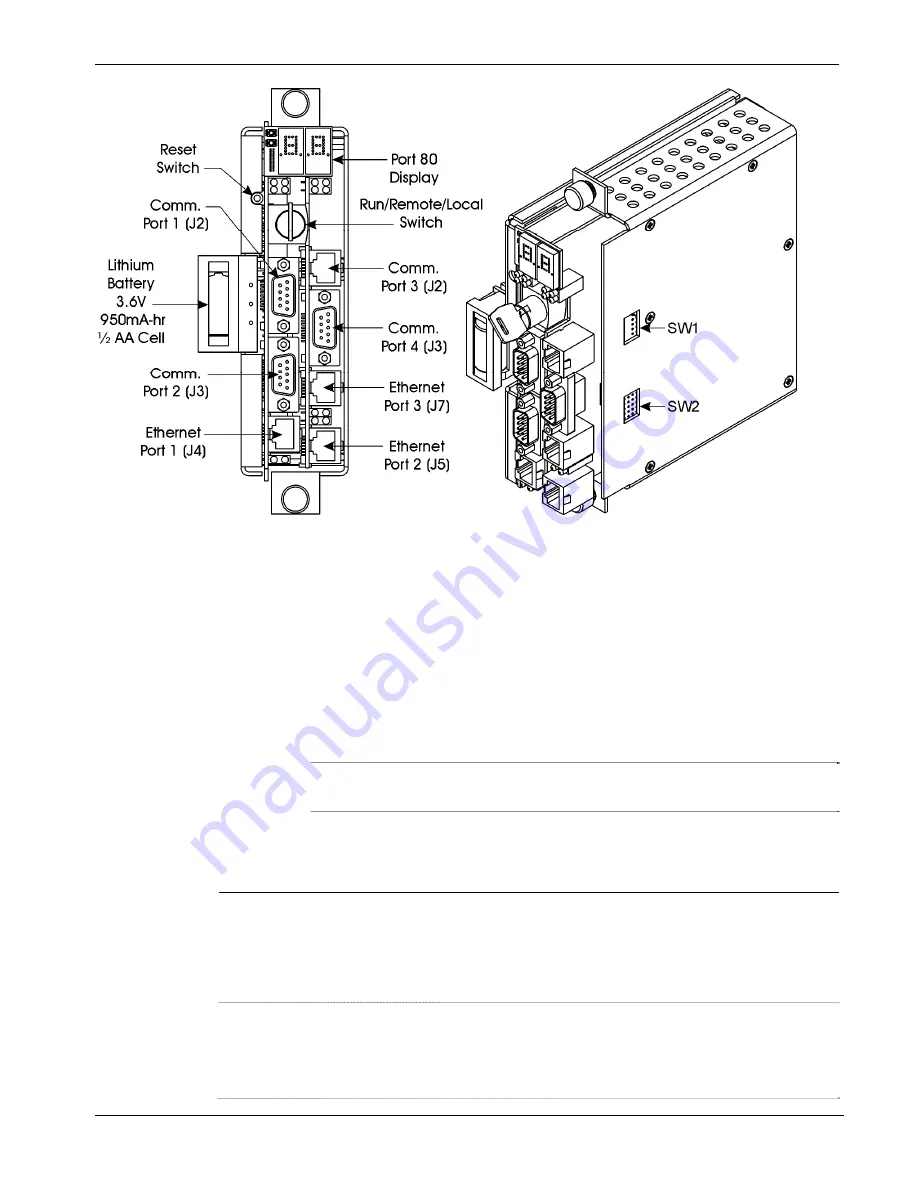
Figure 2-9. ControlWave CPU Module (with SCB)


2.4.1 Setting DIP Switches on the CPU Module 


Before you install the CPU module, you must determine the settings for 
its DIP switches. Refer to 

Figure 2-8 

for the location of the DIP switch 

banks on the CPU board itself. If you have a secondary 
communications board (SCB) you must also refer to 

Figure 2-9

 for the 

location of the DIP switch banks on the SCB. Refer to 

Tables 2-2


through 

2-4

 for DIP switch setting values.  

Note

Examine each bank of DIP switches carefully to note the switch 
direction for ON or OFF.


Table 2-2. CPU Module Switch SW1 

SW1 Setting 

Function 

Mode 

Watchdog 
Enable 

Controls whether the system enters a watchdog state 
when a crash or system hangup occurs and automatically 
restarts. Values are: 

ON

 (Enables watchdog circuit; 

factory default

OFF

 (Disables watchdog circuit and prevents automatic 

restart) 

Lock/Unlock 
Soft Switches 

Controls the ability to modify soft switches, other 
configurations, and flash files. Values are: 

ON

 (Unlocks soft switches and flash files; 

factory 

default

). 

OFF

 (Locks soft switches, configurations, and flash files) 

Revised Nov-2010 

Installation 

2-19 

Summary of Contents for ControlWave

Page 1: ...Instruction Manual Document CI ControlWave Part D301381X012 November 2010 www EmersonProcess com Remote Remote Automation Solutions ControlWave ControlWave Process Automation Controller ...

Page 2: ...turning any equipment to RAS for repairs or evaluation please note the following The party sending such materials is responsible to ensure that the materials returned to RAS are clean to safe levels as such levels are defined and or determined by applicable federal state and or local law regulations or codes Such party agrees to indemnify RAS and save RAS harmless from any liability or damage whic...

Page 3: ...r operation Emerson offers a full schedule of classes conducted by full time professional instructors Classes are offered throughout the year at various locations By participating in our training your personnel can learn how to install calibrate configure program and maintain your Emerson products and realize the full potential of your system For information or to enroll in any class go to http ww...

Page 4: ...This page is intentionally left blank ...

Page 5: ...he PSSM 2 10 2 3 5 Wiring an External Alarm or Annunciator to the Watchdog Connector and Wiring the Redundancy Control Input OPTIONAL 2 15 2 4 CPU Module 2 18 2 4 1 Setting DIP Switches on the CPU Module 2 19 2 4 2 Connections to RS 232 Serial Port s 2 22 2 4 3 Connections to RS 485 Serial Port s on Secondary Communication Board SCB 2 27 2 4 4 Connections to Ethernet Port s on the CPU Module 2 29 ...

Page 6: ... Removing or Replacing Components 5 5 5 2 1 Accessing Modules for Testing 5 5 5 2 2 Removing Replacing the Bezel 5 5 5 2 3 Removing Replacing the CPU Module 5 6 5 2 4 Removing Replacing the PSSM 5 6 5 2 5 Removing Replacing an I O Module Hot Swapping 5 7 5 2 6 Removing Replacing the Backup Battery 5 12 5 3 General Troubleshooting Procedures 5 12 5 3 1 Checking LEDs 5 13 5 3 2 Checking Wiring Signa...

Page 7: ...daptable high performance distributed open controller family with exceptional networking capability that provides a complete process automation management solution for the natural gas water and wastewater industries The ControlWave was designed with an emphasis on providing high performance with low power consumption scalability and modularity Features ControlWave process automation controllers ha...

Page 8: ... Chapter 3 I O Modules Provides general information and wiring diagrams for the I O modules Chapter 4 Operation Provides information on day to day operation of the ControlWave Chapter 5 Service and Troubleshooting Provides information on service and troubleshooting procedures 1 2 Physical Description Each ControlWave has a printed circuit board PCB backplane mounted in a stainless steel housing a ...

Page 9: ...or more I O modules see Section 1 6 and Chapter 3 1 3 Housings ControlWave housings are stainless steel designed for panel mounting or for some versions for mounting in a 19 inch equipment rack They contain the printed circuit board PCB backplane into which you connect the PSSM the CPU module and any I O modules The following housings are available 6 slot backplane supports one PSSM one CPU and up...

Page 10: ...ControlWave Instruction Manual CI ControlWave Figure 1 2 ControlWave Housing Options 1 4 Introduction Revised Nov 2010 ...

Page 11: ...H 32 MB simultaneous read write FLASH memory transmit TX and receive RX LEDs for each communication port Keyed run remote local operation switch configuration DIP switches described in Chapter 2 Port 80 display to show status codes You can order the CPU module with the optional secondary communication board SCB for additional communication ports See CPU Module Configurations CPU Module Configurati...

Page 12: ...ystem Memory SRAM The CPU module has 2 MB of static random access memory SRAM During power loss periods SRAM enters data retention mode powered by the CPU backup battery Critical system information that must be retained during power outages or when the system has been disabled for maintenance is stored here This includes the last states of all I O points audit archive historical data if not stored...

Page 13: ... block to connect the external power supply Watchdog output connector to signal a watchdog failure to an external device Status LEDs Chapter 2 includes instructions for installing and configuring the PSSM 1 6 I O Modules The ControlWave supports analog input analog output digital input digital output universal digital input isolated RTD and isolated low level analog input modules for either local ...

Page 14: ...Module with door open 1 7 Software Tools The ControlWave programming environment consists of a set of integrated software tools which allow you to create test implement and download complex control strategies for use with the ControlWave Figure 1 4 graphically presents the programming environment ...

Page 15: ...control strategy programs called projects are fully compatible with IEC 61131 standards For information on ControlWave Designer see the Getting Started with ControlWave Designer manual document D5085 the ControlWave Quick Setup Guide document D5084 and the ControlWave Designer Programmer s Handbook document D5125 The I O Configurator accessible via a menu item in ControlWave Designer allows you to...

Page 16: ...e data values and communication statistics These controls utilize ActiveX technology and are called through a set of fixed web pages compatible with Microsoft Internet Explorer Alternatively developers can place the controls in third party ActiveX compatible containers such as Visual BASIC or Microsoft Excel For information on the ActiveX controls see the Web_BSI Manual document D5087 User defined...

Page 17: ...s 2 3 4 2 10 Wiring a Bulk DC Power Supply to the PSSM 2 3 5 2 15 Wiring an External Alarm or Annunciator to the Watchdog Connector and Wiring the Redundancy Control Input OPTIONAL 2 4 2 18 CPU Module 2 4 1 2 19 Setting DIP Switches on the CPU Module 2 4 2 2 22 Connections to RS 232 Serial Port s 2 4 3 2 27 Connections to RS 485 Serial Port s on the Secondary Communication Board SCB 2 4 4 2 29 Con...

Page 18: ... I Div 2 Installation Considerations Underwriters Laboratories UL lists the ControlWave as non incendive and suitable only for use in Class I Division 2 Group A B C and D hazardous locations and non hazardous locations Read this chapter and Appendix A carefully before you install a ControlWave in a hazardous location Perform all power and I O wiring in accordance with Class I Division 2 wiring met...

Page 19: ... upon how you order it the ControlWave Micro may arrive pre assembled with all modules installed in the housing or as individual components in a number of separate boxes In the latter case you must identify unpack and assemble the components Unless otherwise noted you can place modules in any slot in a base or expansion housing Note Do not install modules in the housing until you have mounted and ...

Page 20: ... I O unit You can install a ControlWave equipped with an 8 I O module housing in a 19 inch equipment rack a panel or a wall These units ship from the factory with the end plates configured for 19 inch rack mounting Remove the end plates rotate them 180 and then reinstall them to accommodate panel or wall mounting See Figure 2 1 for hole patterns and dimensions When you install any of these units o...

Page 21: ...ControlWave Instruction Manual CI ControlWave Figure 2 1 8 I O Module ControlWave Mounting Diagram Revised Nov 2010 Installation 2 5 ...

Page 22: ...the designated installation site Housings have a ground lug that accommodates up to a 4 AWG wire size Once you install the housing you must run a ground wire between the housing ground lug and a known good earth ground When you install the various ControlWave modules into the housing and secure them using the captured panel fasteners this automatically connects them to chassis ground 2 6 Installat...

Page 23: ...p the length as short as possible Clamp or braze the ground wire to the ground bed conductor typically a stranded copper AWG 0000 cable installed vertically or horizontally Tin the wire ends with solder using a high wattage soldering iron prior to inserting the wire into the housing ground lug Run the ground wire so that any routing bend in the cable has a minimum radius of 12 inches below ground ...

Page 24: ...ControlWave Instruction Manual CI ControlWave Figure 2 3 Power Supply Sequencer Module PSSM 2 8 Installation Revised Nov 2010 ...

Page 25: ...r annunciator if the ControlWave enters a watchdog condition in which the CPU cannot control your process This occurs on power up before the ControlWave project starts if the unit is reset if the ControlWave project crashes or if the system loses power See Section 2 3 5 Redundancy Control Input The same terminal block TB1 used for watchdog control also handles a redundancy control line to a Contro...

Page 26: ...k DC power supply do not connect the pluggable terminal block connectors TB1 and TB2 to the PSSM until after you install wire and configure the CPU module Follow the instructions in Section 2 3 3 General Wiring Guidelines when wiring connections Operating Range The ControlWave operates from 22 2 Vdc to 30 0 Vdc with a nominal 24Vdc input source One or Two Power Supplies You can connect one or two ...

Page 27: ...r module 16 DI Module 1A per module 32 DI Module 1A per module 16 DO Module See table no surge current 32 DO Module See table no surge current 6 UDI Module See table no surge current 4 RTD Module See table no surge current 6 LLAI Module See table no surge current So for example if you have a ControlWave with a 16AI module an 8AO module and a 32DI module the maximum current draw is 1A for the CPU p...

Page 28: ...56 8 mA For 24Vdc supply add 26 1 mA per loop Output at 5 mA Digital Input Module 32 points 29 2 mA 29 7 mA For 24Vdc supply add 4 74 mA per loop dry contact Digital Input Module 16 points 15 8 mA 29 7 mA For 24Vdc supply add 4 74 mA per loop dry contact Digital Output Module 32 points 42 6 mA 0 mA Digital Output Module 16 points 22 6 mA 0 mA Universal Digital Input UDI 6 points 16 7 mA 0 mA Isola...

Page 29: ... wiring at the PSSM s TB1 block Figure 2 4 PSSM Wire Routing Diagram Note As an added precaution we recommend that you run a 14 AWG wire from the TB2 5 power connection chassis ground to the same known good earth ground used for the housing Revised Nov 2010 Installation 2 13 ...

Page 30: ...ControlWave Instruction Manual CI ControlWave Figure 2 5 PSSM TB2 Typical Wiring Schemes 2 14 Installation Revised Nov 2010 ...

Page 31: ...A watchdog timer expires This happens if the ControlWave project execution halts unexpectedly program crash The controller powers up but is not yet running the ControlWave project The CPU module detects that the regulated supplies are out of specification A MOSFET switch activates the watchdog connector whenever a watchdog condition occurs If your ControlWave is part of a redundant pair the Contro...

Page 32: ...he following connections TB1 1 VO Watchdog MOSFET Switch Output TB1 2 VI Watchdog MOSFET Switch Input TB1 3 VR Redundant Unit Control Input The VI input on TB2 TB1 2 powers the watchdog switch its switched output connects to the VO output on the same terminal block TB1 1 You must reference the external power source connected to the VI terminal to the return point of the input source powering the P...

Page 33: ...ControlWave Instruction Manual CI ControlWave Figure 2 7 ControlWave to ControlWave RED I O Redundancy Field Wiring Revised Nov 2010 Installation 2 17 ...

Page 34: ...ype CPU with two RS 232 serial ports and one Ethernet port No SCB CPU with two RS 232 serial ports and one Ethernet port SCB with one additional RS 232 port one RS 485 port and two additional Ethernet ports CPU with two RS 232 serial ports and one Ethernet port SCB with one additional RS 232 and an RS 485 port CPU with two RS 232 serial ports and one Ethernet port SCB with two RS 485 ports Set DIP...

Page 35: ...tch setting values Note Examine each bank of DIP switches carefully to note the switch direction for ON or OFF Table 2 2 CPU Module Switch SW1 SW1 Setting Function Mode 1 Watchdog Enable Controls whether the system enters a watchdog state when a crash or system hangup occurs and automatically restarts Values are ON Enables watchdog circuit factory default OFF Disables watchdog circuit and prevents...

Page 36: ...r situation or a power outage Values are ON Retain values in SRAM during restarts factory default OFF Reinitialize SRAM Data in SRAM lost during power outage or re start 6 Redundancy Enable Disable Specifies whether this ControlWave is part of a redundant pair Values are ON Redundancy Disabled Not part of redundant pair factory default OFF Redundancy Enabled This ControlWave is one of two in a red...

Page 37: ...e real time clock Values are ON enables backup battery OFF disables backup battery This is the factory default Note The unit ships from the factory with the backup battery disabled to conserve battery power Set this to ON when you install the CPU Notes Table 2 4 describes switch settings for ports on the SCB board You may want to review Section 2 4 3 before you set these switches Table 2 4 applies...

Page 38: ... 7 Not currently used ON RX bias end node OFF Not an end node factory default 8 Not currently used ON RX bias end node OFF Not an end node factory default After you set the DIP switches and insert the CPU module in slot 2 of the housing you can connect communication ports 2 4 2 Connections to RS 232 Serial Port s An RS 232 port provides point to point half duplex and full duplex communications for...

Page 39: ...t Cables For the ControlWave half duplex communications use BSAP protocol or another protocol such as Modbus while full duplex communications use point to point protocol PPP RS 232 ports use a null modem cable see Figure 2 12 to connect with other devices such as a PC a printer another ControlWave except the CW_10 30 35 when the ControlWave uses the full duplex PPP protocol If you don t want to ma...

Page 40: ...e Data Input 3 TXD Transmit Data Output 4 DTR Data Terminal Ready Output 5 GND Signal Power Ground 6 DSR Data Set Ready Input 7 RTS Request to Send Output 8 CTS Clear to Send Input 9 RI Ring Indicator Figure 2 11 shows the RJ 45 connector used for COM3 on the SCB If you ordered COM3 as an RS 232 port see Table 2 8 for pin assignments Figure 2 11 RJ 45 Connector Associated with COM3 SCB 2 24 Instal...

Page 41: ...ale D Connector P1 3 TXD 6 DSR 7 RTS 8 CTS 4 DTR 2 RXD 1 DCD 5 GND 3 TXD 6 DSR 7 RTS 8 CTS 4 DTR 2 RXD 1 DCD 5 GND To P2 Pin 4 To P2 Pin 2 To P2 Pin 7 To P2 Pin 3 To P2 Pin 6 To P2 Pin 5 To P2 Pin 1 or vice versa 3 TXD 6 DSR 7 RTS 8 CTS 4 DTR 2 RXD 1 DCD 5 GND 3 TXD 6 DSR 7 RTS 8 CTS 4 DTR 2 RXD 1 DCD 5 GND To P2 Pin 2 To P2 Pin 3 To P2 Pin 5 or vice versa CW 9 Pin Female D Connector P2 CW 9 Pin F...

Page 42: ...male D Connectors 3 TXD 7 RTS 8 CTS 4 DTR 2 RXD 1 DCD 5 GND To TXD To RXD To RTS To CTS To GND 3 TXD 8 CTS 4 DTR 2 RXD 1 DCD 5 GND 7 RTS To From MODEM To From RADIO Figure 2 14 Connecting to a Modem or Radio When COM3 on the secondary communications board SCB is an RS 232 port you use an RJ 45 connector to connect to other devices See Figure 2 15 Looking into Connector Intf Side of P1 Pin 1 Wht Gr...

Page 43: ...tions to multiple nodes up to 4000 feet away If you purchased your CPU module with a secondary communication board SCB you may have either one or two RS 485 ports RS 485 COM Port Names and Connectors RS 485 COM ports are assigned names based on their location in the ControlWave COM3 on the SCB board can be purchased as either an RS 232 port or as an RS 485 port COM4 on the SCB board is always an R...

Page 44: ...9 Since the RS 485 port is intended for network communications refer to Table 2 12 for the appropriate connections for wiring the master first slave and nth slave Essentially the master and the first slave transmit and receive data on opposite lines all slaves from the first to the nth are paralleled daisy chained across the same lines Wire the master node to one end of the RS 485 cable run using ...

Page 45: ...ons to Ethernet Port s on the CPU Module The ControlWave can support from one to three Ethernet ports These use a 10 100Base T RJ 45 modular connector that provides a shielded twisted pair interface to an Ethernet hub Two LEDs per port provide transmit and receive status indications Table 2 13 shows port assignments for the Ethernet ports Table 2 13 Ethernet Ports Connector Name Function Notes J4 ...

Page 46: ...ut using a hub However you must configure the cable so that the TX Data pins connect to the RX Data pins swapped at the opposite ends of the cable see Figure 2 18 Figure 2 18 Point to Point 10 100Base T Ethernet Cable The maximum length of one segment CPU to hub is 100 meters 328 feet The use of Category 5 shielded cable is recommended 2 5 Bezels The bezel is a blue plastic cover see Figure 2 19 t...

Page 47: ...modules If necessary you can remove the bezel for maintenance procedures To install the bezel align the snaps on the bezel with the corresponding holders on the chassis Once you have it positioned push gently and the bezel snaps into place To remove the bezel gently grasp its sides and pull out and away from the chassis Figure 2 19 Bezel Assembly Revised Nov 2010 Installation 2 31 ...

Page 48: ...This page is intentionally left blank ...

Page 49: ...same basic steps 1 Remove the I O module from the shipping carton I O modules include a removable terminal housing assembly This assembly has a door that swings downward to provide access to the unit s terminal handle you can use to remove an installed I O module once you loosen the captured panel fasteners Note Modules normally ship from the factory completely assembled 2 Turn the terminal block ...

Page 50: ...he I O module turning the quarter turn fasteners clockwise 6 Replace the module s terminal housing assembly Figure 3 1 Terminal Housing Assembly Removal 7 Using a PC running the ControlWave Designer and OpenBSI software configure the ControlWave to accept the new I O modules and download the revised ControlWave project Note This step is beyond the scope of this manual Refer to the ControlWave Desi...

Page 51: ... safe use of this product please review and follow the instructions in the following supplemental documentation Supplement Guide ControlWave Site Considerations for Equipment Installation Grounding and Wiring S1400CW ESDS Manual Care and Handling of PC Boards and ESD Sensitive Components S14006 WARNING NEVER ATTEMPT hot swapping in a Class I Division 2 hazardous location 3 1 Module Placement You c...

Page 52: ...f the I O modules include one or more light emitting diodes LEDs to provide diagnostic or status indications See Chapter 5 for information on the different LEDs 3 3 Wiring With a few exceptions noted in the module descriptions I O modules support either local termination field wiring connected directly to the 3 4 I O Modules Revised Nov 2010 ...

Page 53: ...d with solder to prevent flattening and improve conductivity Allow some slack in the wires when making terminal connections Slack makes the wires more manageable and helps minimize mechanical strain on the terminal blocks 3 2 1 Local Termination For I O modules equipped with local terminal blocks install the field wiring between the I O module s removable terminal block connectors and field device...

Page 54: ...he DIN rail mounted terminal blocks out through the bottom of the I O module between the header block and the terminal housing assembly To provide access to the header block s lower turn fastener use a tie wrap to secure cables associated with connectors P3 and P4 to the lower left side of the header block assembly Use a second tie wrap to secure cables for connectors P1 and P2 to the lower right ...

Page 55: ...ControlWave Instruction Manual CI ControlWave Revised Nov 2010 I O Modules 3 7 Figure 3 4 I O Module Remote Termination Wire Routing ...

Page 56: ...ut filtering Dedicated LED on module turns ON when DI is ON A DI module consists of a digital input printed circuit board PCB with either a terminal block assembly for local termination or a header block assembly for remote termination Each DI module also includes an LED board as well as I O assembly and mounting hardware The DI PCB connects to the backplane using a 110 pin connector Detailed Tech...

Page 57: ...Table 3 3 Jumper Assignments DI Module Jumper Purpose Description WI Configures DI1 Pins 2 3 4 5 installed External Power DI Pins 1 2 3 4 installed Internal Source DI W2 W32 Configures DI2 through DI32 respectively Same as W1 Wiring the Module Figure 3 6 shows field wiring assignments associated with locally terminated DI modules Figure 3 9 shows field wiring assignments associated with remotely t...

Page 58: ...anual CI ControlWave 3 10 I O Modules Revised Nov 2010 Figure 3 6 DI Module Local Terminal Block Assembly Assignments Figure 3 7 Internally Sourced DI Module Wiring Diagram Figure 3 8 Externally Powered DI Module Wiring Diagram ...

Page 59: ...bly Assignments Software Configuration To use data from any ControlWave DI module you must add a CW_DI32 board in ControlWave Designer s I O Configurator and then configure it See the ControlWave Designer Programmer s Handbook D5125 for more information That same manual includes an I O Mapping section that describes for advanced users the I O map for this module ...

Page 60: ...ControlWave Instruction Manual CI ControlWave Figure 3 10 Remote DIN Rail Mountable Terminal Block Assembly Assignments for Relay Isolated 120Vac DI Operation 3 12 I O Modules Revised Nov 2010 ...

Page 61: ...e Configurations The DO module general part number 396358 XX X comes in several possible configurations see Table 3 5 Table 3 5 Isolated DO Module Configurations Part Number Number of DOs Termination Connector Notes 396358 01 2 32 Local 396358 02 0 16 Local 396358 11 0 32 Remote 396358 12 8 16 Remote 396358 20 9 16 Remote DO with read back Outputs set OFF on power up An on board DO load register s...

Page 62: ... details on setting up DO with readback Wiring the Module Figure 3 11 shows field wiring assignments associated with a locally terminated DO module Figure 3 12 shows a wiring diagram for the DO Field wiring assignments associated with remotely terminated DO modules Figure 3 13 shows field wiring assignments for a remotely terminated DO module Figure 3 14 shows a special remote termination module w...

Page 63: ...lWave Instruction Manual CI ControlWave Revised Nov 2010 I O Modules 3 15 FUSES F0 to F7 1A F 2A Figure 3 13 Remote DIN Rail Mountable Terminal Block Assembly Assignments for Open Source Isolated DO Operation ...

Page 64: ...te DIN Rail Mountable Terminal Block Assembly Assignments for Relay Isolated 24Vdc DO Operation Software Configuration To use data from any ControlWave DO module you must add a CW_DO32 board in ControlWave Designer s I O Configurator and then configure it See the ControlWave Designer Programmer s ...

Page 65: ...he I O slot number of the virtual ER_STAT board and x is the I O slot number of the digital output module See the I O Configurator and I O Mapping sections of the ControlWave Designer Programmer s Handbook D5125 for more information You can optionally rename these variables You should configure these variables as alarms so you receive notification of a failure of the backup DO module See the Contr...

Page 66: ...nt a failover and the only reporting is via the _RDN_IO_x_ERR system variables and LEDs discussed above For boards residing in an I O expansion rack instead of a system variable for this purpose you must map a variable from the _ER_STAT virtual status board named either ERSTAT_RDN_IOERR_WARN or ERST_RDN_IOERR_WARN NOTE Those are the default names you can change them as needed Note In the I O Confi...

Page 67: ...ts reference VFxx of the module Analog input circuitry isolated from bus interface Surge suppression and signal conditioning Cable Shields Connect cable shields associated with AI wiring to the ControlWave housing ground Multiple shield terminations require that you supply a copper ground bus up to a 4 AWG wire size and connect it to the housing s ground lug This ground bus must accommodate a conn...

Page 68: ...A 396352 11 1 16 Remote 4 20 mA 396352 13 8 8 Remote 4 20 mA 396352 14 6 8 Remote 1 5 Vdc Wiring the Module Figure 3 18 shows terminal assignments for a locally terminated AI module Figure 3 19 and Figure 3 20 show terminal assignments for a 4 20mA and a 1 5Vdc remotely terminated AI respectively Figure 3 15 Internally Sourced 4 20mA Current Loop AI Wiring Diagram Figure 3 16 Externally Powered 4 ...

Page 69: ...Blocks Assembly Assignments Software Configuration To use data from any ControlWave analog input module you must add a CW_AI16 board in ControlWave Designer s I O Configurator and then configure it See the ControlWave Designer Programmer s Handbook D5125 for more information That same manual includes an I O Mapping section that describes for advanced users the I O map for this module ...

Page 70: ...ControlWave Instruction Manual CI ControlWave 3 22 I O Modules Revised Nov 2010 FUSES F0 F2 F4 F6 1 8A Figure 3 19 Remote DIN Rail Mountable Terminal Block Assembly Assignments for 4 20 mA AI Operation ...

Page 71: ...ControlWave Instruction Manual CI ControlWave Revised Nov 2010 I O Modules 3 23 FUSES F0 F2 F4 F6 1 8A Figure 3 20 Remote DIN Rail Mountable Terminal Block Assembly Assignments for 1 5V AI Operation ...

Page 72: ...e AO values of its standby counterpart in order to verify that standby AO values are consistent should a failover occur Depending upon software configuration settings a failover can be prevented if they are inconsistent A standard AO module used in a redundant system does not perform this monitoring therefore the potential exists to failover to a backup AO module with failed hardware For critical ...

Page 73: ...l 4 20mA 396353 11 8 8 remote 4 20mA 396353 20 7 8 remote 4 20mA AO Readback on this module Wiring the Module Figure 3 21 shows field wiring assignments for a locally terminated AO module Figure 3 22 shows field wiring assignments for a remotely terminated AO module Figure 3 21 Local AO Module Terminal Blocks Assembly Assignments Revised Nov 2010 I O Modules 3 25 ...

Page 74: ...ControlWave Instruction Manual CI ControlWave 3 26 I O Modules Revised Nov 2010 FUSES F0 F2 F4 F6 1 8A Figure 3 22 Remote DIN Rail Mountable Terminal Block Assembly Assignments for AO 4 20mA Operation ...

Page 75: ...tion on configuring system variables is included in the ControlWave Designer Programmer s Handbook D5125 If there is a difference of more than 0 5 of span between the value of the online and standby AO values a variable will be set TRUE For local I O boards this is a system variable that follows the format _RDN_IO_n_ERR where n is the I O slot number of the AO module For boards residing in an I O ...

Page 76: ... another system variable _RDN_IOERR_WARN determines whether a failure of the standby AO as indicated by the LED and associated _ERR error variable should only be treated as a warning condition which would still allow a failover to occur or as an error which would prevent a failover to the standby When you set this system variable to FALSE an AO readback failure in the associated device is treated ...

Page 77: ...tput or a relay contact Inputs handle 24V Jumper to configure point for debounce enable or debounce disable Software configures point as a polled input with a 30 millisecond filter or as a 16 bit high speed counter totalizer with a 20 microsecond filter Maximum input frequency of 10 KHz with a nominal input current of 5mA 16 bit counter Signal conditioning circuitry and bandwidth limiting circuitr...

Page 78: ... a jumper to enable disable debounce Enabling debounce activates filters that reduce spurious pulses caused by relay contact bounce Figure 3 24 shows the location of jumpers on the module Front Right Side Terminal Housing Ass y 1 820 6 457 6 970 1 1 W1 W2 W3 W4 W5 W6 W7 W9 W10 W11 W12 W8 1 1 1 1 1 Jumper locations Figure 3 24 UDI Module Right Side View Jumper Locations 3 30 I O Modules Revised Nov...

Page 79: ... 1 2 installed Enable Debounce Factory default A change of state on both the SET and RST reset field inputs is required to accumulate counts Pins 2 3 installed Disable Debounce A change of state on the SET field input is required to accumulate counts Wiring the Module Figure 3 27 shows field wiring assignments for the locally terminated UDI module It also includes examples for relay contact and op...

Page 80: ...OM5 HSCRST5 HSCSET2 HSCCOM2 HSCRST2 HSCSET4 HSCRST4 HSCCOM4 HSCSET6 HSCCOM6 HSCRST6 Terminal Block Assembly Assignments for UDI Operation FIELD Field CIRCUITRY TB HSCSET HSCCOM HSCRST 1 5 3 Relay Contact FIELD CIRCUITRY Field TB HSCSET HSCCOM 1 3 A Open Collector or Relay Contact B Figure 3 27 Local UDI Terminal Block Configuration Diagram ...

Page 81: ...le that interfaces with Remote UDI Module s DIN Rail Mountable Terminal Block Assembly UDI1 UDI3 UDI4 UDI6 A Top TB N A UDISET1 UDIRST1 UDICOM2 UDISET3 UDIRST3 B Bottom TB 0 2 4 6 _ 1 3 5 7 N A UDICOM1 UDISET2 UDIRST2 UDICOM3 UDIRST3 _ N A UDISET4 UDIRST4 UDICOM5 UDISET6 N A B Bottom TB 0 2 4 6 1 3 5 7 UDIRST6 UDICOM4 UDISET5 UDIRST5 UDICOM6 UDIRST6 _ FUSE F0 FUSE F2 FUSE F4 FUSE F6 _ FUSES F0 F2 ...

Page 82: ...ype in ControlWave Designer I O Configurator Choose one of the following HSC Channel to select a 20 microsecond delay for 10 kHz high speed counter applications 1 MS to select a 1 millisecond delay for a low speed counter application 30 MS to select a 30 millisecond delay for a polled input This is for general purpose inputs or contacts where contact bounce may apply See the ControlWave Designer P...

Page 83: ... system bus Source current to RTD limited to 330 uA The RTD Input Module consists of an isolated RTD input board a terminal board assembly for local termination or a header block assembly for remote termination an LED board a terminal housing assembly as well as I O assembly and mounting hardware Detailed Technical Specifications For additional technical specifications please see document CWPAC av...

Page 84: ...isolated RTD modules Figure 3 30 provides wiring diagrams for 2 wire 3 wire and 4 wire RTDs to the local RTD module terminal blocks wiring assignments such as RTD _3 4W RTD _4W RTD and RTD are similar to those assigned to the Remote DIN rail mountable terminal blocks Note To maintain specified accuracy with a 3 wire RTD you must match the two field wires that source and sink the RTD current within...

Page 85: ...ta from an Isolated RTD Input module you must add a CWM_RTD8 board in ControlWave Designer s I O Configurator and then configure it See the ControlWave Designer Programmer s Handbook D5125 for more information That same manual includes an I O Mapping section that describes for advanced users the I O map for this module Revised Nov 2010 I O Modules 3 37 ...

Page 86: ...ControlWave Instruction Manual CI ControlWave Figure 3 32 Remote DIN Rail Mountable Terminal Block Assembly Assignments for Isolated RTD Module Operation 3 38 I O Modules Revised Nov 2010 ...

Page 87: ...ect to chassis 24 bit analog to digital converter ADC Detailed Technical Specifications For additional technical specifications please see document CWPAC available on our website http www emersonprocess com remote Configuration The isolated LLAI module general part number 396877 XX X has the following configurations Table 3 17 Isolated Low Level Analog Input LLAI Module Configurations Part Number ...

Page 88: ...ture compensation at the terminal block and is electrically isolated Pins 8 9 and 10 of the local terminal block source and sink the CJC s RTD Figure 3 35 also provides diagrams showing the wiring for thermocouples and the 3 wire RTDs to a locally terminated LLAI module Wiring assignments that is AI AI CJC Sense CJC Return CJC Reference are similar to those assigned to the remote DIN rail mountabl...

Page 89: ...ControlWave Instruction Manual CI ControlWave Revised Nov 2010 I O Modules 3 41 Figure 3 34 Local Isolated LLAI Module Terminal Block Assembly Assignments ...

Page 90: ...ControlWave Instruction Manual CI ControlWave 3 42 I O Modules Revised Nov 2010 Figure 3 35 Remote DIN Rail Mountable Terminal Block Assembly Assignments for Isolated LLAI Module Operation ...

Page 91: ... 09 C 8 C 4 C 2 C 1 C 0 500 C 10 C 8 C 4 C 2 C 1 C J Thermocouple 210 C to 191 C 190 C to 1200 C 0 08 C 0 11 C 0 750 C 0 500 C 1 5 C 1 C E Thermocouple 270 C to 260 C 260 C to 225 C 225 C to 200 C 200 C to 1000 C 1 00 C 0 25 C 0 08 C 0 09 C 3 C 1 C 0 750 C 0 500 C 6 C 2 C 1 5 C 1 C K Thermocouple 270 C to 261 C 260 C to 246 C 245 C to 180 C 179 C to 145 C 145 C to 1372 C 2 00 C 0 56 C 0 25 C 0 08 ...

Page 92: ...46 C to 222 C 220 C to 160 C 159 C to 25 C 25 C to 1372 C 15 00 C 4 50 C 2 20 C 1 10 C 0 55 C 0 30 C T 270 C to 261 C 260 C to 243 C 242 C to 196 C 195 C to 61 C 60 C to 25 C 25 C to 400 C 10 30 C 3 00 C 1 50 C 0 75 C 0 375 C 0 30 C Note Use straight line approximation to calculate approximate error between end points Software Configuration To use data from an Isolated Low Level Analog Input modul...

Page 93: ...ct 4 5 4 4 Creating and Maintaining Backups 4 5 1 4 5 Creating a Zipped Project File ZWT 4 5 2 4 6 Saving Flash Configuration Parameters FCP 4 5 3 4 8 Backing up Data 4 1 Powering Up Powering Down the ControlWave Open the bezel door on the PSSM and use the power switch to turn the ControlWave ON or OFF Power switch 1 ON O OFF Figure 4 1 Power Switch on PSSM 4 2 Setting the Operating Mode Run Remot...

Page 94: ...Local switch to Local enables communications through any comm port However if you set the switch to Remote that restricts communications only to comm ports configured as remote comm ports 4 3 Communicating with the ControlWave You communicate to the ControlWave by connecting a cable between a port on your PC workstation and one of the ControlWave ports See Section 2 4 for more information on commu...

Page 95: ... as DataView Data Array Save Restore and Harvester allow you to collect real time data values of variables array values alarm messages and historical data audit records archive files from the ControlWave See the OpenBSI Utilities Manual D5081 for details SCADA software such as OpenEnterprise can then present this data to an operator in the form of graphical displays and reports 4 4 Creating and Do...

Page 96: ...Backups You should always maintain a current backup of each ControlWave project and keep it in a safe place preferably in a location physically separate from the controller The reason we recommend you keep a backup files is that if a disaster occurs that damages or destroys your ControlWave hardware flood lightning strike etc you don t want to also lose its control strategy software programs Other...

Page 97: ...ter time for editing With your current ControlWave project open in ControlWave Designer perform the following steps 1 Click File Save Project As Zip Project As Figure 4 3 Saving a Backup of Your Project 2 In the Save Zip project as dialog box specify a project name in the File name field In Figure 4 3 we chose the name mynewproj 3 In the Save as type field choose Zipped Project Files zwt 4 In the ...

Page 98: ...s the percent complete of the zipping process 6 When the zip process completes you ll see a message box reporting successful completion Click OK 7 Copy the resulting zwt file to backup media CD ROM thumb drive etc If you ever need to restore the project just open the zwt file in ControlWave Designer load libraries as needed then compile the project and download it into the ControlWave 4 5 2 Saving...

Page 99: ...therwise just proceed to step 3 3 Click and wait for the utility to retrieve all parameters from the ControlWave 4 Click and specify a name for your FCP file then click Save When the status line indicates successful completion your FCP file in done 5 Copy the resulting FCP file to backup media CD ROM thumb drive etc If you ever need to restore the FCP parameters to the controller establish communi...

Page 100: ...ers setpoints for example you can use tools such as the OpenBSI DataView recipe feature to save those values to a recipe file on the PC and then restore them at a later time See Chapter 8 of the OpenBSI Utilities Manual D5081 You can store the contents of read write data arrays using the OpenBSI Data Array Save Restore utility See Chapter 13 of the OpenBSI Utilities Manual D5081 You can collect al...

Page 101: ...Diagnostic Utility 5 4 1 5 28 Available Diagnostics 5 5 5 32 Core Updump Equipment You need the following equipment to perform the procedures described in this chapter To run diagnostics software PC with WINDIAG software and either OpenBSI LocalView NetView or TechView for communications Null modem interface cable Loop back plug for RS 232 port see Figure 5 21 Loop back plug for RS 485 port see Fi...

Page 102: ...ition Note For further information and detailed use instructions refer to Appendix J of the OpenBSI Utilities Manual D5081 LocalView One of the standard OpenBSI utilities LocalView requires OpenBSI version 5 1 or newer If you have an older version of OpenBSI use HyperTerminal Note For further information and detailed use instructions refer to the Flash Mode section of Chapter 5 of the OpenBSI Util...

Page 103: ...n Self Test Unless there is a problem you should see the code 86 on the Port 80 display If you see a different status code see Section 5 3 3 6 From the HyperTerminal Mode menu Figure 5 1 press the F key to enter FLASH download A message warns that the FLASH is about to be erased press the Y key at the prompt The screen displays dots as the system erases the flash memory this could take a few minut...

Page 104: ...m release to release and click Send to start the flash upgrade see Figure 5 4 When you see the HyperTerminal Mode Menu again it means the download has completed 9 Exit HyperTerminal and power down the ControlWave If desired you can disconnect the null modem cable between the ControlWave and the PC 10 Set CPU switch SW3 3 to OFF Recovery Mode Disabled 11 Restore power to the ControlWave Figure 5 3 ...

Page 105: ... warranty Return defective modules or housings to the factory for authorized service 5 2 1 Accessing Modules for Testing Only technically qualified personnel should test and or replace ControlWave modules Read completely the disassembly and test procedures described in this manual before starting Any damage to the ControlWave resulting from improper handling or incorrect service procedures is not ...

Page 106: ...l or otherwise identify them so you can easily return them to their assigned communication ports 4 Remove the bezel See Section 5 2 2 5 Loosen the two captured panel fasteners that secure the CPU module to the chassis and carefully slide it out the front of the chassis You may need to rock the board back and forth gently to do this 6 To replace a CPU module the PSSM must already reside in slot 1 b...

Page 107: ...and insert the module into the housing When the module correctly seats in the backplane turn the module s captured panel fasteners clockwise to secure the PSSM module this establishes a low resistance path between the PSSM module and chassis ground Make sure the fasteners are tight but don t over tighten them 8 Replace the CPU module 9 Replace power and watchdog cables and then apply power and tes...

Page 108: ...running place any critical control processes that use this I O module under manual control 2 Loosen the capture fasteners at the top and bottom of the module by turning them counter clockwise Loosen the capture fasteners at the top and bottom of the module Figure 5 5 I O Module to Be Replaced 3 Open the bezel door and grasp the handle Pull the entire module out of the chassis 5 8 Service Troublesh...

Page 109: ...odule with a new module but want to retain all your existing I O wiring to the terminal blocks you need to disconnect the terminal block board from the rest of the module To do that loosen the screws at the top and bottom of the terminal block board Then grab the handle and pull the terminal block board along with the terminal housing assembly off of the front of the module ...

Page 110: ...Loosen the fasteners at the top and bottom of the terminal board Figure 5 7 Loosening the Top Fastener Figure 5 8 Terminal Block Board and Terminal Housing Assembly Separated from the Rest of the Module 5 10 Service Troubleshooting Revised Nov 2010 ...

Page 111: ...e fasteners but not too tight Figure 5 9 New I O Module in Place Prior to Attaching Terminal Board and Terminal Housing Assembly 7 Take the terminal block board and terminal housing assembly with all the I O wiring that you removed in step 4 and line up its fasteners with the holes on the module now seated in the housing and gently push the terminal block board and terminal housing assembly into t...

Page 112: ...l the ControlWave has been in service for an extended period normally many years Caution You lose SRAM contents when you remove the backup battery or its assembly from the CPU module If you replace a backup battery or its assembly wait at least one minute before re powering the system This enables the SRAM to completely discharge Removing Replacing the Battery 1 If the ControlWave is running place...

Page 113: ...ft of LED cluster in Figure 5 11 CPU CR3 COMM 1 TX Red ON TX transmit activity on COMM1 See top right of LED cluster in Figure 5 11 CPU CR3 COMM 2 RX Red ON RX receive activity on COMM2 See bottom left of LED cluster in Figure 5 11 CPU CR3 COMM 2 TX Red ON TX transmit activity on COMM2 See bottom right of LED cluster in Figure 5 11 CPU CR8 ENET Port 1 Red Green ON RED Data Collision Left see Figur...

Page 114: ... board not recognized ON GREEN Normal state See Figure 5 12 AI Range 16 LEDs one per point Red LED ON AI over range or AI under range condition See Figure 5 12 AI Range 16 LEDs one per point Green LED ON AI in range See Figure 5 12 AO AO Board status fail Red LED ON AO board fail state board not recognized See Figure 5 13 AO AO Board status pass Green LED ON AO board normal or O K state Figure 5 1...

Page 115: ...oint Green LED ON LLAI in range See Figure 5 18 1 3 I O Red Red Green MC LED PWRFAIL LED PWRGOOD LED TB1 Watchdog Connector TB2 Input Power Connector POWER SWITCH Captured Panel Fastener Captured Panel Fastener 1 5 1 5 VIN 22 2Vdc to 30Vdc for 24V supply VINF Connected to TB2 1 or separate 20 0Vdc to 30Vdc supply VIN 1st Supply Ground VINF 2nd Supply Ground Internally connected to TB2 3 Chassis Gr...

Page 116: ...ontrolWave Instruction Manual CI ControlWave 5 16 Service Troubleshooting Revised Nov 2010 Figure 5 11 CPU Module CPU SCB boards Port LED Designations Figure 5 12 Analog Input AI Module LED Designations ...

Page 117: ...ControlWave Instruction Manual CI ControlWave Revised Nov 2010 Service Troubleshooting 5 17 Figure 5 13 Analog Output AO Module LED Designations ...

Page 118: ...ControlWave Instruction Manual CI ControlWave 5 18 Service Troubleshooting Revised Nov 2010 Figure 5 14 Digital Input DI Module LED Designations Figure 5 15 Digital Output DO Module LED Designations ...

Page 119: ...XX Input is present FAIL Red UDI Bd Status LED PASS Green UDI Bd Status LED UNIVERSAL DIGITAL INPUT Note The Status LED will turn ON Red whenever power is initially applied to the UDI Module It will remain Red until the CPU has recognized the UDI Module and then it will turn Green and should remain ON Revised Nov 2010 Service Troubleshooting 5 19 UNIVERSAL DIGITAL INPUT Figure 5 16 Universal Digit...

Page 120: ...ControlWave Instruction Manual CI ControlWave Figure 5 17 RTD Module LED Designations 5 20 Service Troubleshooting Revised Nov 2010 ...

Page 121: ...respective terminal blocks see Table 5 2 Table 5 2 I O Field Wiring Terminal Block Reference I O Module or sub system Notes Digital Input Modules See Section 3 4 Digital Output Modules See Section 3 5 Analog Input Modules See Section 3 6 Analog Output Modules See Section 3 7 Universal Digital Input UDI Modules See Section 3 8 RTD Input Modules See Section 3 9 Low Level Analog Input Modules See Sec...

Page 122: ...wait kbd ctrllr 07 cksum okay kbd ctrllr free 08 verifying BAT cmd to kbd ctrllr 09 issuing kbd ctrllr cmd byte 0A issuing kbd ctrllr data byte 0B issuing pin 23 24 blocking unblocking 0C issuing kbd ctrllr NOP cmd next 0D testing CMOS RAM shutdown register 0E checking CMOS cksum updating DIAG byte 0F initializing CMOS if req d every boot 10 Init CMOS status reg for date time 11 disabling DMA inte...

Page 123: ...und at 0 0 45 checking for wrap find total memory size 46 write extended memory test patterns 47 write conventional memory test patterns 48 finding low memory size from patterns 49 finding high memory size from patterns 4A check ROM BIOS data area again 4B check for DEL clear low mem for soft reset 4C clearing ext mem for soft reset 4D saving memory size 4E on cold boot display 1st 64KB memtest 4F...

Page 124: ...6 initialization before calling C800h 97 call ROM BIOS extension at C800h 98 processing after extension returns 99 configuring timer data area printer base addr 9A configuring serial port base addrs 9B initialization before coprocessor test 9C initializing the coprocessor 9D processing after coprocessor initialized 9E check ext kbd kbdID numlock settings 9F issue keyboard ID command next A0 kbd ID...

Page 125: ...s CF Invalid Checksum Detected Unit Stopped D0 Diagnostic Mode SW1 8 OFF D1 Running Diagnostic DE User Application has failed to start Invalid I O Card configuration F0 NPX Error Unit Stopped F1 Waiting for Power down After NMI FA CPU Bd Switch SW1 3 Set OFF Ignore Soft Switch Configuration Use factory defaults Flashes for 1 second At startup FC Waiting for Alt Watchdog Timer Unit Stopped FD Waiti...

Page 126: ...actory defaults this sets all serial ports to 9600 baud in preparation for the diagnostic tests Use a null modem cable to connect RS 232 ports between the ControlWave and the PC Use an RS 485 cable to connect the RS 485 ports of the ControlWave and the PC Note For information on port connections and cabling please see Chapter 2 See Section 4 3 1 for information on communication port defaults Reser...

Page 127: ...gure 5 19 NetView 2 Select Start OpenBSI Tools Common Tools Diagnostics The Main Diagnostics menu Figure 5 20 displays Figure 5 20 WINDIAG Main Diagnostics Menu 3 Select the module to be tested Enter any prompted parameters slot etc WINDIAG performs the diagnostics and displays pass fail results ...

Page 128: ...hecks AOs on the Analog Output module High Speed Counter Checks the Universal Digital Input UDI module Prom Ram Checks the CPU s RAM and PROM hardware Analog Input Checks AIs on the Analog Input module Communications Checks Communication ports 1 through 4 The loop back tests require the use of a loop back plug Discrete I O Checks DIs on Digital Input Module DOs on Digital Output Modules Ethernet C...

Page 129: ...hown in left side of Figure 5 22 Port 4 RS 485 use a 9 pin female D type loop back plug shown in right side of Figure 5 22 These tests verify the correct operation of the communication interface on ports COM1 through COM4 Note You cannot test a communications port while you are using it You can only test currently unused ports After you complete testing on all other communication ports and verify ...

Page 130: ... COM4 2 Select Communications on the WINDIAG Main Diagnostics Menu The Communications Diagnostic screen opens Figure 5 23 Communications Diagnostic Menu 3 Enter 5 in the Number of Passes field 4 Select a port to test click to display all available ports Note The port you select must correlate to the port on which you placed the loop back plug in step 1 5 Select 115200 or ALL ASYNC as the baud rate...

Page 131: ...form the Ethernet loop back test Figure 5 24 RJ 45 Ethernet Loop back Plug Note You cannot test a communications port while you are using it You can only test currently unused ports After you complete testing on all other communication ports and verify their correct functioning you must reconnect using a now validated port and test the remaining untested port Test Procedure Use this procedure to t...

Page 132: ...t the loop back plug and reconnect the Ethernet cable to the ControlWave and the Ethernet hub 7 Click Return to Menu to display the WINDIAG Main Menu 5 5 Core Updump In some cases such as when a ControlWave fails for no apparent reason you can upload a copy of the contents of SRAM and SDRAM to a PC for support personnel and service engineers to evaluate This upload is called a core updump A core u...

Page 133: ... the ControlWave Comm Port 1 to a PC using a null modem cable 4 Operate the Run Remote Local switch as follows Note You must perform each step in less that one second a Set Run Remote Local switch to Run b Set Run Remote Local switch to Remote c Set Run Remote Local switch to Local d Set Run Remote Local switch back to Remote e Set Run Remote Local switch back to Local 5 Start the PC s HyperTermin...

Page 134: ...updump completes set the failed unit s CPU switch SW1 1 to ON and SW1 4 to ON if required and then power cycle the failed unit to receive the sideload to become a valid standby unit This applies to the ControlWave REDIO as well 5 34 Service Troubleshooting Revised Nov 2010 ...

Page 135: ...llow the instructions in this appendix 2 All power and I O wiring must be performed in accordance with Class I Division 2 wiring methods as defined in Article 501 4 b of the National Electrical Code NFPA 70 for installations within the United States or as specified in Section 18 152 of the Canadian Electrical Code for installation in Canada WARNING EXPLOSION HAZARD Substitution of components may i...

Page 136: ...This page is intentionally left blank ...

Page 137: ...ly the loss of both power supplies on the redundant power supply sequencer module would trigger a failover Caution There is a slight difference between the two redundant power supplies One uses a black anodize bracket the other a gold irridite bracket Should a power supply fail you must use a replacement supply that has an identical bracket assembly black anodize or gold irridite The RPSSM must ha...

Page 138: ...tchdog circuitry This is the default Watchdog wiring is discussed later in this document 2 3 Disables the watchdog circuitry JP2 1 2 Sets the RPSSM as always the on line unit This is the default Use this setting if the RPSSM is not installed in a redundant system 2 3 Specifies that the RPSSM is part of a redundant system Choose this position if the RPSSM is installed In a ControlWave Redundant Con...

Page 139: ... When disabled the RPSSM does not report a failure if voltage falls below 12V If you need to change the jumper positions unscrew the protective case from the RPSSM using a Phillips screwdriver see Figure P 2 Figure P 2 Removing the Protective Case from the RPSSM Revised Nov 2010 Installation and Use P 3 ...

Page 140: ...ly to the RPSSM An external 24V power supply 22 2 to 30V connected to TB1 provides system power to the ControlWave including the CPU boards and I O boards see Figure P 4 Note Be sure you route wires to the terminal block connectors so they do not interfere with removal replacement of the power supply modules Figure P 4 Wiring System Power to the RPSSM An external power supply 22 2 to 30V connected...

Page 141: ...iring The VI input of the terminal block TB3 6 powers the watchdog switch Its switched output connects to the VO output of the terminal block TB3 5 Reference the external power source connected to the VI terminal to the return point of the input source that powers the RPSSM VIN TB1 2 RPSSM connector TB3 provides watchdog switch and redundancy control connections as follows Connections TB3 5 VO Wat...

Page 142: ...he A I O expansion rack RPSSM to TB2 1 on the IORCM and TB2 2 on the IORCOM to 24V Similarly wire terminal block connector TB3 7 on the B I O expansion rack RPSSM to TB2 3 on the IORCM and TB2 4 on the IORCOM must to 24V Figure P 8 shows the location of the IORCM connectors on the ControlWave I O Switcher Figure P 7 ControlWave to ControlWave REDI O Redundancy Field Wiring P 6 Installation and Use...

Page 143: ...l Input to Indicate Power Supply Failure Power Supply Digital Input Internally Sourced Digital Input Externally Sourced 1 TB3 1 SYSTEM GND TB3 2 DIGITAL INPUT TB3 1 SYSTEM PWR TB3 2 DIGITAL INPUT 2 TB3 3 SYSTEM GND TB3 4 DIGITAL INPUT TB3 3 SYSTEM PWR TB3 4 DIGITAL INPUT Hot swapping a Power Supply WARNING DO NOT ATTEMPT hot swapping in a Class I Division 2 hazardous location Each power supply has...

Page 144: ...pplies first turn the power supply s ON OFF switch off the down position as shown in Figure P 9 Loosen the plastic screw either by hand or with a Phillips screwdriver Grasp the bracket and gently pull the power supply straight out of the assembly Figure P 9 Hot Swapping a Power Supply To re insert the power supply grasp the bracket and line up the board with the grooves in the assembly Gently slid...

Page 145: ...ng as power to unit remains within normal operating ranges MC Master Clear Red Lights when the CPU is not running and I O has been reset to 0 This lights momentarily when the unit first powers on or when the unit resets PWR DOWN Red Lights when power has fallen below acceptable levels Figure P 10 LED Locations Each power supply on the RPSSM also has an LED which lights when power is good If this L...

Page 146: ...ating 40 to 85 o C Storage 40 to 85 o C Relative Humidity 15 to 95 non condensing Vibration 1G for 10 150 Hz 0 5 G for 150 Hz to 2000 Hz RFI Susceptibility 3V m 80 MHz to 1000 MHz per EN50082 2 Watchdog MOSFET 1A Power Supplies 1 or 2 on the RPSSM Input Range 20 to 30Vdc 24V input supply nominal Output Voltage 5V 2 3 3V 2 Output Current 1A 3 3V 2A 5V Efficiency 80 at full load Fusing 7x2 mm fuse 3...

Page 147: ...tails on these hazards please contact the manufacturer for the most recent material safety data sheet Manufacturer General Description Emerson Part Number Media Notes Eagle Picher http www eaglepicher com Lithium Thionyl Chloride Battery 1 2 AA 3 6V 950 mAh On board 395600 01 4 Eagle Picher P N LTC 9C SAFT America http www saftbatteries com Lithium Thionyl Chloride Battery 1 2 AA 3 6V 950 mAh On b...

Page 148: ...This page is intentionally left blank ...

Page 149: ... RAM memory amount 1 6 color code of connectors 2 4 Communication Ports defaults 4 2 Ethernet 2 29 Loop back Test 5 28 5 30 5 31 RS 232 2 22 RS 485 2 27 Communications protocols supported 1 10 ControlWave project downloading 4 3 Core Updump See Updump CPU Module 1 5 description 1 5 Installation 2 18 Lithium battery backup 5 12 Removing 5 6 Replacing 5 6 switches 2 19 Current calculating maximum re...

Page 150: ...ezel Assembly 2 31 3 1 Terminal housing assembly removal 3 2 3 2 ControlWave Chassis Slot Assignments 3 4 3 3 I O Module local termination wire routing 3 5 3 4 I O Module Remote Termination Wiring 3 7 3 5 DI Module right side view jumper locations 3 9 3 6 DI Module Local Terminal block assembly assignments 3 10 3 7 Internally sourced DI Module wiring diagram 3 10 3 8 Externally powered DI module w...

Page 151: ...terminal block assy assignments 3 42 4 1 Power Switch on PSSM 4 1 4 2 Run Remote Local Key Switch 4 2 4 3 Saving a Backup of Your Project 4 5 5 1 HyperTerminal Mode Menu 5 3 5 2 HyperTerminal Ready to Download 5 4 5 3 Send File dialog box 5 4 5 4 HyperTerminal Download in progress 5 5 5 5 I O Module to Be Replaced 5 8 5 6 Pulling the I O Module Out of the Housing 5 9 5 7 I O Loosening the Top Fast...

Page 152: ...ng 5 7 Replacing 5 7 RTD 3 35 UDI 3 29 Wiring 3 5 Input Accuracy and Resolution LLAI Module 3 43 Installation 2 1 3 6 Class 1 Div 2 2 2 CPU 2 18 I O Modules 3 3 Overview 2 2 PSSM 2 7 J Jumpers DI 3 9 LLAI 3 39 RPSSM P 2 RTD 3 35 UDI 3 30 L LEDs Checking 5 13 on RPSSM P 9 Local termination 3 5 LocalView 5 2 Loop back Test 5 28 5 30 Low Level Analog Input Module 3 39 CJC Error 3 43 Input Accuracy an...

Page 153: ...ration switches 2 21 RS 485 ports 2 27 cables for 2 27 configuration switches 2 21 RTD See Resistance Temperature Device RTD Input Module Run Remote Local switch 4 1 Running diagnostic software 5 25 S SDRAM memory amount 1 6 Service 5 1 Shielding 3 6 Site Considerations 2 1 Soft Switches Lock unlock 2 19 Software used with the ControlWave 1 8 Specifications for temperature humidty vibration 2 2 SR...

Page 154: ...olated RTD Input Module General Characteristics 3 35 3 14 Isolated RTD Input Module Configurations 3 35 3 15 Jumper Assignments Non isolated HSC Module 3 36 3 16 Isolated LLAI Module General Characteristics 3 39 3 17 Isolated LLAI Module Configurations 3 39 3 18 Jumper Assignments Isolated LLAI Module 3 39 3 19 LLAI Module Input Accuracy and Resolution 3 43 3 20 LLAI Module RTD Error with CJC at 2...

Page 155: ...ControlWave Instruction Manual CI ControlWave IND 7 Index Revised Nov 2010 DO 3 14 for redundancy 2 15 I O Modules 3 5 LLAI 3 40 PSSM 2 10 RPSSM P 4 RTD 3 36 UDI 3 31 watchdog circuit 2 15 2 16 ...

Page 156: ...CT TO THIS MANUAL AND IN NO EVENT SHALL RAS BE LIABLE FOR ANY INCIDENTAL PUNITIVE SPECIAL OR CONSEQUENTIAL DAMAGES INCLUDING BUT NOT LIMITED TO LOSS OF PRODUCTION LOSS OF PROFITS LOSS OF REVENUE OR USE AND COSTS INCURRED INCLUDING WITHOUT LIMITATION FOR CAPITAL FUEL AND POWER AND CLAIMS OF THIRD PARTIES Bristol Inc Bristol Babcock Ltd Bristol Canada BBI SA de CV and the Flow Computer Division are ...

Reviews: