


Manual: R1300-X-00-X_EN Release: 1.04 © Elotech GmbH Page 2/20
I.
Contents
I.
Contents ....................................................................................................... 2
II.
Type Code .................................................................................................... 2
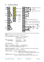
III.
Connection Diagram ..................................................................................... 3
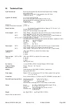
IV.
Technical Data .............................................................................................. 4
V.
Display and Keyboard .................................................................................. 5
VI.
Operating Levels .......................................................................................... 6
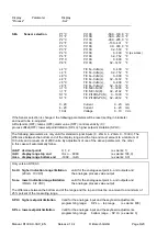
VII.
Configuration Level ....................................................................................... 7
VIII.
Parameter Level ......................................................................................... 13
IX.
Operating Level .......................................................................................... 17
X.
Error displays .............................................................................................. 19
XI.
Installation Instructions ............................................................................... 19
Please read this operating manual carefully before starting up.
Observe the installation and connecting instructions.
Take care to the separat interface- and data transmission descriptions.
Only trained personnel following the regional safety regulations may operate the hereby discribed
instruments. It is essential, that one has well experience in installing electric devices.
The instrument is not suitable for installation in hazardous areas.
Do not open the device while the power lines are connected.
Before operation, the unit must be configurated for its intended purpose under an expert guidance.
(e.g. controller type, sensor type and range, alarm adjustment etc.)
See:
„Configuration Level“ and „Parameter Level”
Attention:
The „heating“- or „cooling“-outputs can be active while programming or configuring
the controller. This can cause a damage either to the plant itself or its contents.
Disclaimer of liability
We have checked the contents of the document for conformity with the hardware and software described. Nevertheless, we are unable
to preclude the possibility of deviations so that we are unable to assume warranty for full compliance. The information given in the
publication is, however, reviewed regularly. Necessary amendments are incorporated in the following editions.
We would be pleased to receive any improvement proposals which you may have.
This document may not be passed on nor duplicated, nor may its contents be used or disclosed unless expressly permitted. Violations
of this clause will necessarily lead to compensation in damages.
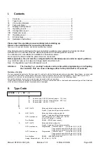
II.
Type Code
R 1300 - x - 00 - z
1:
Power supply: 230 VAC (internal jumper : 115 V ac)
2:
Power supply: 115 VAC (internal jumper : 230 V ac)
2:
Power supply: 24 VDC , +/- 20%
1:
OUT1, OUT2:
Relay and bistab. voltage output for
2-point-, 3-point- and 3-point-step-controller
2:
OUT1, OUT2:
Relay and bistab. voltage output for
2-point-, 3-point- and 3-point-step-controller
OUT4, continuous:
Controller output: 0/4...20mA, 0/2...10 VDC
to control "heating" or "cooling"
Ser. Interface:
RS 485 (RS232 upon request)
3:
OUT1, OUT2:
Relay and bistab. voltage for
2-point-, 3-point- and 3-point-step-controller
OUT4, continuous:
Programable: Controller output 0/4...20mA, 0/2...10 VDC
Process value output 0/4...20mA, 0/2...10 VDC
Setpoint value output 0/4...20mA, 0/2...10 VDC
OUT5, continuous:
Programable: Controller output 0/4...20mA, 0/2...10 VDC
Process value output 0/4...20mA, 0/2...10 VDC
Setpoint value output 0/4...20mA, 0/2...10 VDC
Ser. Interface:
RS 485 (RS232 upon request)
Analog. Setpoint-Input:
0/4...20mA, 0...10 VDC


