background image

45

English

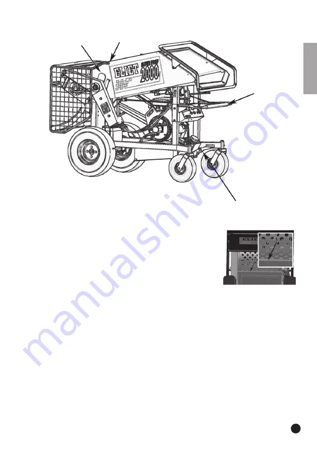
A. Lubrication of pivot points and friction surfaces

This group includes the following locations on the machine:

Ground drive control pivot points
Ball joints of the hydraulic valves
Nylon sealing plates for the feed roller guides
Throttle control lever pivot point
Choke lever
Quick-closing sieve screening system
Screen locking pin
Pivot points of the safety guard
Wheel drive brake guide
Parking brake foot pedal

Use the following procedure :

• Whenever possible, disassemble the hinge or the joint.
• Spray some penetrating oil containing molybdenum disulphide onto the frictions surfaces and 

allow the oil to penetrate.

• Wipe away all traces of old lubricant and dirt.
• In the event of some parts not being accessible, use compressed air to remove all traces of old 

lubricant and dirt (e.g. in the joints of pivot points).

• When the pivot points are clean, apply new lubricant.
• ELIET recommends Novatio Clearlube as a lubricant for pivot points and ball joints. ELIET would 

recommend Novatio PFT grease for friction surfaces.

• Wipe away any excess lubricant.

Summary of Contents for MA 006 010 113

Page 1: ...Superprof M A N U A L...

Page 2: ...2 English...

Page 3: ...machine in the boxed areas Product code Serial Number Year of Manufacture Date of purchase 2 Warranty 2 1 Warranty card To be eligible to obtain warranty you must mail the completed warranty card with...

Page 4: ...n if you are thoroughly familiar with operating such equipment it is still advisable to read these pages carefully At ELIET all our machines and devices are subjected to a policy of continuous change...

Page 5: ...haust system in such a manner that flames or heat from the system will not ignite flammable material Failure of the owner operator of the equipment to comply with this regulation is a misdemeanour und...

Page 6: ...ies of the operator 17 7 3 4 Personal protective equipment 18 7 3 5 Risk zone 18 7 3 6 Periodic maintenance 18 7 3 7 Preserving nature 19 8 Dealer preparation 19 9 Safety instructions 20 9 1 Prelimina...

Page 7: ...nal battery acid 36 11 4 Machine maintenance 37 11 4 1 Checking and sharpening the blades 37 11 4 2 Reversing and renewing the shredding knives 39 11 4 3 Checking the drive belt for correct tension 41...

Page 8: ...formation and or actions or to denote where you can find additional information relating to the subject 5 2 Caution Caution This notice identifies safe usage habits This is done to prevent incorrect a...

Page 9: ...rts identi fied by name It is a good idea to take time to study the machine beforehand for an improved understanding of the descriptions provided in this user manual 1 Safety handle 2 Wheel drive cont...

Page 10: ...ranch feed of the machine Your ELIET dealer is at your service ready to provide you with maintenance or advice so that your ELIET machine always remains in optimal condition You can contact him for ge...

Page 11: ...tectors Performing maintenance or operating the machine can be source of hand injuries Be attentive and careful Sticker 2 reminds the user to keep by standers a safe distance away 10m Sticker 1 affixe...

Page 12: ...screen has been eased away This decal is affixed to the back of the machine at the safety screen This sticker reminds the user of the machine to examine the bolts retaining the blades for security of...

Page 13: ...mmediately renewed Stickers are available at your approved ELIET Dealer The following stickers apply exclusively to our American Customers This sticker summarizes in 18 items a number of important saf...

Page 14: ...of problems Order Number BQ 505 010 240 7 2 Safety provisions Safety screen The safety screen 1 avoids access to the blades No tools are required to open the screen but the motor is shut off on open...

Page 15: ...ition 3 If you move the handle to position 2 the feed roller pulls the material into the machine If you move the handle to position 1 the feed roller rotates in the opposite direction so that any mate...

Page 16: ...observe all safety instructions when using the ELIET machine Carefully read all the instructions relating to the use of the machine All these instructions relate to your personal safety When you purc...

Page 17: ...machine form mov ing For deontological reasons ELIET accept no responsibility whatsoever for any accidental injury to pets or persons caused by its machines 7 3 3 Responsibilities of the Operator All...

Page 18: ...rea When leaving the machine the engine must be switched off Always wait until the blades come to a complete standstill before carrying out any operation Once the engine is running focus all your atte...

Page 19: ...is something cannot be over em phasized All the bolts retaining the blades must be examined for security of fixings after the first 5 operating hours Torque loading 40Nm Likewise make sure to check th...

Page 20: ...actures in a blade this blade must be immediately renewed see Chapter 11 4 2 Reversing and renewing the shredding knives For safety s sake tighten the balde bolts see the list in annex for bolt torque...

Page 21: ...hing at once It is unsafe and thus expressly forbidden to fill the fuel tank in the vicinity of smokers or naked flames Iffuelcomesintocontactwiththeeyesoristakeninternally obtainmedicalattentionimmed...

Page 22: ...throttle control lever 1 to the mid position Close the choke lever 2 by pulling the knob Turn the ignition key 3 to the 1 position and make sure the red oil level pilot light 4 comes on This lets you...

Page 23: ...hat the safety handle is in the neutral position Moving the machine Move the control handle forwards then the machine will move forwards The more you move the control handle forwards the faster the sp...

Page 24: ...o become acquainted with the characteristics of a self propelled machine and do so in a quiet spacious location without bystanders Note You can move the throttle control lever to increase the speed of...

Page 25: ...on Always shred at full throttle for the engine to produce its full power output Move the control lever to the centred position position 2 The feed roller starts to turn and pulls the garden waste int...

Page 26: ...ou position 3 When the engine returns to its normal speed you can restart the feed roller by moving the control handle to the centre position position 2 With ABM The feed roller stops when engine spee...

Page 27: ...ing steps Stop the feed roller by pushing the control handle to position 3 Move the throttle control lever to the minimum position Stop the engine using the ignition key Remove any foreign objects If...

Page 28: ...fouled spark plug Blades are blunt Incorrect tension of V belt 9 7 6 Wheel drive does not operate when petrol engine is running Safety handle is not in neutral position Defect in the hydraulic circuit...

Page 29: ...ve grease and lubricants use penetrating oil containing molybdenum disulphide This spray lubricates and also dissolves rust It is useful to have compressed air in the vicinity so that you can use it t...

Page 30: ...ve down backwards facing the machine If gravity causes the machine to descend more quickly down the slope than is desired quickly move the control handle to the other drive direction This enables you...

Page 31: ...n detail Caution Only use genuine ELIET replacement parts These service parts are manufactured to the same strict quality control requirements and degree of craftsmanship as the original equipment For...

Page 32: ...and lubricants His staff can always obtain advice and service from ELIET so that they can provide you with an impeccable after sales service 11 2 General interventions Warning For your own safety Afte...

Page 33: ...safety guard 1 upwards Pull the lock 2 downwards Make sure that both clamps 3 are re leased Topple the shredding screen 4 downward To completely remove the sieve perform the following steps Remove the...

Page 34: ...ing up the oil Remove the filler cap and remove the dipstick so that the crankcase is ventilated Caution Topping off the oil level is a meticulous job do not overfill the reservoir to extend engine li...

Page 35: ...h the filter Remove the used filter 1 after allowing the oil to drain if stubborn use an oil filter wrench Apply a film of new oil to the sealing gasket of the new filter Screw the new filter onto the...

Page 36: ...ch off the engine and remove the ignition key from the ignition switch Warning Always allow the machine to cool down this is to avoid fire hazard or danger of explosion Loosen the retaining straps 2 a...

Page 37: ...r discomfort seek prompt medical attention Wash your hands immediately after performing this maintenance Note NEVER add additional acid add only distilled water 11 4 Machine maintenance 11 4 1 Checkin...

Page 38: ...erformed by moving the grinding disc along the angled cutting edge Avoid excessive grinding in the same location prevent local discoloration of blades this denotes heating that causes the material str...

Page 39: ...lades as a pair as shown in the photos in order to work in an organised manner Disassemble the blades by removing the two M8 bolts from each blade In this situation always use two ring spanners fitted...

Page 40: ...e of each blade of group 2 mounted on a fluted part of a blade disc must point towards the centre axis When this is not the case adjust B To renew a shredding knife proceed as follows New sets of kniv...

Page 41: ...badly installed blades can pose a danger to the operator and the machine If this happens you are no longer covered by the warranty 11 4 3 Checking the drive belt for correct tension Remove the belt g...

Page 42: ...tal plates between the engine block and the guide bolts 5 6 and screw the guide bolts until they just touch the engine block Lock the guide bolts using the lock nuts M10 SW 17 11 4 5 Checking the tens...

Page 43: ...rrect tension and turn the clamping bolt 3 further inwards or outwards if track tension is too high Remember to tighten the lock nut 2 to secure the clamping bolt 3 As you go along thoroughly clean an...

Page 44: ...hance of a hydraulic defect and premature wear 11 4 8General lubrication In view of the fact that the shredders often operate in extreme conditions ELIET considers it im portant to use high quality ma...

Page 45: ...Use the following procedure Whenever possible disassemble the hinge or the joint Spray some penetrating oil containing molybdenum disulphide onto the frictions surfaces and allow the oil to penetrate...

Page 46: ...is sufficient to distribute the grease Wipe away any grease that comes out of the joints C Lubricating the bearings This group includes the following locations on the machine Bearing of the feed rolle...

Page 47: ...in and around the drive Use penetrating oil containing molybdenum disulphide to dissolve the lubricant When the drive is clean and all traces of grease and dirt have been removed you can apply new lub...

Page 48: ...arting up the new machine Within the first 5 hours after rotating the blades Within the first 5 hours after changing the blades What Check all blade bolts for correct torque loading and retighten if c...

Page 49: ...fore performing any maintenance stop the engine and remove the key from the ignition switch Wear suitable clothing Daily maintenance see Chapter 11 5 3 Change the engine oil see Chapter 11 3 2 Clean t...

Page 50: ...itable clothing Maintenance after 100 hours see Chapter 11 5 5 Change RESISTTM blades if fitted see Chapter 11 4 2 Changing the hydraulic oil and oil filter see Chapter 11 4 7 Air cleaner change see C...

Page 51: ...the machine At ELIET we strongly recommend that the machine is stored at a location that is well protected from the weather etc When winterizing the machine for long periods it is recommended to perfo...

Page 52: ...uard Open the sieve by pulling the clamp backwards 1 Make sure that the hooks are com pletely released Remove the hairpin clip 2 Pull the rod 3 out and remove the sieve from the machine Change the sie...

Page 53: ...ng the belt conveyor to the machine always be sure to switch off the engine Remove the safety guard cover M8 SW13 Warning The cover is part of the safety guard and prevents you from coming into contac...

Page 54: ...Remove the locking pin 2 first and then press the control handle down Note After machine start up first switch on the discharge belt conveyor before feeding branch es into the feeding hopper Detaching...

Page 55: ...crewing this transverse beam Loosen the M8 bolts on either side SW13 Move the transverse beam to another attachment hole and then refit the bolts Tighten the bolts so that the belt conveyor remains se...

Page 56: ...that you can evaluate the result of your action If the conveyor tracks to the left then perform the above procedure but replace left with right Checking the conveyor belt for correct tracking Perform...

Page 57: ...ler 23 m min Infeed opening W H 660 x 510 mm Feed in height 1 005 mm 1 000 mm Frame 3 mm and 4 mm steel plate Finish Epoxy polyester Wheels Rear wheels pneumatic tyres 600 x 9 6 ply Tracks 180 x 37 x...

Page 58: ...his knowledge the necessary steps have been taken in line with Machine Directive 2006 42 EC in order to ensure absolute operator safety for the operator when the machine is used correctly The value of...

Page 59: ...51524 Part 3 HVLP Viscosity ISO VG 46 cSt Capacity of hydraulic system 15 L Brands SUNOCO Sunvis 846 WR HV ELF Hydrelf DS 46 SHELL Tellus TD 46 TOTAL Equivis ZS 46 CASTROL Anvol WG 46 TEXACO Rando HDZ...

Reviews: