65
Operating Guide
PSI 8000 3U HS PV Series
EN
Date: 20-05-2016
Operating the device
9. Digital interfaces
9.1 General
The power supply supports various optionally available interface
cards for digital or analog remote control. All cards are galvani-
cally isolated. Following isolation voltages are given:
•
USB (IF-U1), CAN (IF-C1), RS232 (IF-R1): 2000 V DC
•
GPIB (IF-G1): 2000 V DC
•
Ethernet (IF-E1B): 1500 V DC
•
Extended analog interface (IF-A1): 2000 V DC
Note
Before picking an interface for remote control, consider the
isolation voltage and carefully check if the particular isolation
voltage is sufficient for the target application!
The digital interface cards IF-R1 (RS232), IF-C1(CAN) and IF-
U1(USB) use a uniform communication protocol. Up to 30 units
can be controlled from a PC at once with these cards.
The GPIB interface IF-G1 (IEEE 488) offers a SCPI command
structure for up to 15 units per bus.
The Ethernet/LAN interface IF-E1 also provides SCPI command
set, as well as a browser surface. It features an additional USB
port which makes the device accessible like with the IF-U1 card.
The interface card IF-A1 is an extended analog interface, which
features a higher isolation voltage than the built-in analog
interface, as well as variable input voltage range and much
more. For more information, please refer to the interface cards
operating guide, which is supplied on the CD that is included
with the interface or available upon request or on our website.
9.2
Configuring the interface card
If there is interface card equipped, the device will detect it au-
tomatically. The device displays the card with its product code
and article number. Settings can be accessed via the menu
+
Communi
.
Except for the analog interface card IF-A1 and the Ethernet
card IF-E1B it is necessary to set the unit’s address when us-
ing a digital interface card. Only then the unit can be identified
correctly:
Slot:
{ IF-… }
depends on what is equipped
Device node
Default:
1
= {1..30}
Up to 30 device nodes (addresses) can be as-
signed to devices, one per unit. A device node
must only be assigned once if multiple units are
controlled.
Configuring the various cards
All cards have different parameters to configure. These are
explained in detail in the corresponding operating guide. Please
refer to it.
10. Internal analog interface
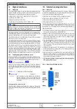
10.1 General
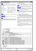
The integrated, galvanically isolated (for isolation voltage see
), 15 pole analog interface is located
on the rear and offers following features:
•
Remote control of output current, voltage and power
•
Remote monitoring of status (OT, OVP, CC, CV)
•
Remote monitoring of actual values
•
Remotely switching the output on/off
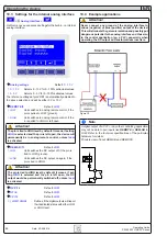
The set value inputs can be operated with either 0...5 V or 0...10
V. The desired voltage range is selected in the device setup
(see section „10.3. Settings for the internal analog interface“).
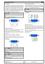
Usage instructions:
•
Controlling the device with analog voltages requires to switch
it to remote control with pin „REMOTE“ (5).
•
Before connecting the application that is used to control the
power supply, make sure to wire all cables correctly and
check if the application is unable to put in voltages higher
than specified (max. 12 V).
•
The input REM-SB (remote standby, pin 13) overrides the
pushbutton
ON
. It means, the output can not be switched on
by the button if the pin defines the output state as „off“. This
does not apply, if the control location was set to
local
. Also
see section 6.9.
•
Putting in set values up to 10 V while the 0...5 V range is se-
lected will ignore any voltage above 5 V (clipping) and keep
the output value at 100%.
•
Remote control is not possible if the user has switched the
device to U/I/R mode on a model where internal resistance
control is unlocked. The internal resistance set value can not
be controlled by analog interface!
•
The whole interface is galvanically isolated against the
DC output of the device
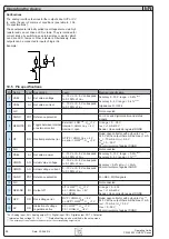
10.2 Overview D-Sub socket


