68
© 2006, Elektro-Automatik GmbH & Co. KG
Irrtümer und Änderungen vorbehalten
EN
Operating Guide
PSI 8000 3U HS PV Series
Date: 20-05-2016
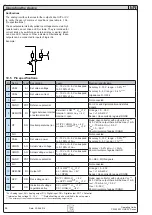
10.5
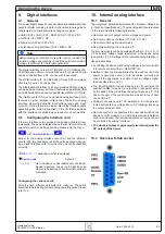
Pin specifications
Pin Name
Type* Description
Level
Electrical specification
1 VSEL
AI
Set value: voltage
0…10 V or 0...5 V correspond
to 0..100% of U
Nom
Accuracy 0...10 V range: < 0.2% ****
Accuracy 0...5 V range: < 0.4% ****
Impedance R
i
>100 k
2 CSEL
AI
Set value: current
0…10 V or 0...5 V correspond
to 0..100% of I
Nom
3 N.C.
Not connected
4 DGND
POT Reference potential
For +Vcc and digital control and status
signals
5 REMOTE
DI
Toggle between internal
or external control
External = LOW***, U
Low
<1 V
Internal = HIGH, U
High
> 4 V
Internal = open
U range = 0 …30 V
I
Max
= +1 mA at 5 V
Sender: Open collector against DGND
6 OT
DO Overtemperature error OT/PF = HIGH, U
High
> 4 V
no error = LOW***, U
Low
<1 V
Quasi open collector with pull-up to Vcc **
At 5 V at the output there will be max.+1 mA
I
Max
= -10 mA at U
CE
= 0.3 V
U
Max
= 0...30 V
Short-circuit-proof against DGND
7 N.C.
Not connected
8 PSEL
AI
Set value: power
0…10 V or 0...5 V correspond
to 0..100% of P
Nom
Accuracy 0...10 V range: < 0.5% ****
Accuracy 0...5 V range: < 1% ****
9 VMON
AO Actual value: voltage
0…10 V or 0...5 V correspond
to 0..100% of U
Nom
Accuracy < 0.2% at I
Max
= +2 mA
Short-circuit-proof against AGND
10 CMON
AO Actual voltage: current 0…10 V or 0...5 V correspond
to 0..100% of I
Nom
11 AGND
POT Reference potential
For -SEL, -MON signals
12 N.C.
Not connected
13 REM-SB
DI
Output off
off = LOW***, U
Low
<1 V
on = HIGH, U
High
> 4 V
on = OPEN
U range = 0…30 V
I
Max
= +1 mA at 5 V
Sender: Open collector against DGND
14 OVP
DO Overvoltage error
OVP = HIGH, U
High
> 4 V
no OVP = LOW***, U
Low
<1 V
Quasi open collector with pull-up to Vcc **
At 5 V at the output there will be max.+1 mA
I
Max
= -10 mA at U
ce
= 0.3 V
U
Max
= 0...30 V
Short-circuit-proof against DGND
15 CV
DO Indication of voltage
regulation active
CV = LOW***, U
Low
<1 V
CC = HIGH, U
High
>4 V
* AI = Analog input, AO = Analog output, DI = Digital input, DO = Digital output, POT = Potential
** Internal pull-up voltage 13...14 V *** Default setting, can be modified in the setup menu
**** The accuracy of the pin adds to the accuracy of the corresponding output value
Notifications
The analog interface features further outputs like OVP or CV
to notify the user of alarms or conditions (see table in „10.5.
These outputs are internally pulled to a voltage source via a high
resistor and can not drive a LED or lamp. They‘re intended for
current intake by switching an external relay or similar, which
can drive LED, lamps or other indicators. Alternatively, these
outputs can be connected to inputs of logic ICs.
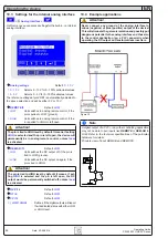
Example:
10k
12V
+
Operating the device

