71
Operating Guide
PSI 8000 3U HS PV Series
EN
Date: 20-05-2016
Operating the device
Fall time
Together with the rise time, this is an important value regarding
the output voltage dynamics. This value is primarily depending
on the load‘s resistance.
Rise time
Together with the fall time, this is an important value regarding
the output voltage dynamics. This values is depending on the
output capacity, the load‘s resistance and the adjusted current
limit.
12.3 General operation instructions
Permanent remote control which results in a big ∆U/∆t is al
-
lowed, as long as a certain total internal power dissipation loss
is not exceeded. It is calculated with the formula dU
max
=
√
(F
/ f) (if frequency is given) or f
max
= F / dU² (if voltage difference
is given) and with F = 192000 for permanent pulsed operation,
whereas f is the frequency of the pulsed operation, dU the
voltage difference of the rising or falling edge and F a factor.
Permanent pulsed operation here means for hours or days.
Short-time operation, e.g. some minutes followed by a break of
the same period, allows higher load dynamics with F = 256000.
Recommended minimum output voltage resp. minimum actual
power the device should be operated with. Below these values
the output ripple is expected to be even higher than stated in
the table above.
12.4
Specific instructions for the 1500 V
model
Extreme pulse-shaped unload, for example 90% I
nom
-> 5% I
nom
,
can produce a voltage rise of up to +100 V. Otherwise, a voltage
rise of 40 V…60 V is typical.
The time of the falling edge is load-dependent. With, for exam-
ple, 1 A constant load t
fall
will be ~67 V/ms, at no-load condition
it is always 1.7 s down to 0 V.
12.5
Altered technical specifications
Model
600 V / 70 A
1000 V / 30 A
1500 V / 30 A
Output capacity C
Out
34 µF
22.5 µF
15 µF
HF ripple constant voltage operation (BW=20 MHz)*
<3 V
pp
<600 mV
pp
<1.5 V
pp
LF ripple constant voltage operation (BW=20 MHz)*
<2.2 mV
pp
<60 mV
pp
<1 V
pp
Ripple constant voltage operation (BW=300 kHz)*
<700 mV
eff
<160 mV
eff
<270 mV
eff
HF ripple constant voltage operation (BW=20 MHz)*
<300 mA
pp
<30 mA
pp
<40 mA
pp
NF ripple constant voltage operation (BW=20 MHz)*
<4000 mA
pp
<8 mA
pp
<40 mA
pp
Ripple constant voltage operation (BW=300 kHz)*
<180 mA
eff
<10 mA
eff
<14 mA
eff
Regulation 10%...90% I
Max
** (in CV)
<4 ms
<2 ms
<2 ms
Regulation 90%...10% I
Max
** (in CV)
<4 ms
<3 ms
<2 ms
Rise time t
Rise
for 10%...90% U
Nom
(no load)
<1,2 ms
<3,2 ms
<1 ms
Rise time t
Rise
for 10%...90% U
Nom
(70% load)
<1,6 ms
<4 ms
<1.2 ms
Recommended f
Max
for ∆U pulsed operation
250 Hz
150 Hz
500 Hz
Fall time t
Fall
for 100%...10% (1% ohmic load)
<190 ms
<350 ms
non-critical
Possible voltage overshoot (pulsed operation)
up to 150 V
up to 150 V
up to 100 V
Recommended U
min
> / P
min
>
40 V/100 W
40 V/160 W
60 V/240 W
* Measured at U
out
>10% and P
out
>5%
** I
Max
is either equal to I
Nom
(for devices without power limitation) or I
Max
= P
Set
/U
Set
(for devices with power limitation)
13. Other applications
13.1 Parallel connection in Share bus mode
Share bus operation is used to gain a symmetric load current
distribution when running multiple units in parallel connection.
Important
: in this operation mode, the unit with the highest
output voltage controls and defines the output voltage of the
whole parallel connection. It means, any unit of the system
could be in charge. Thus it recommended to pick a unit that is
used to control the whole system, while the set value of voltage
for the remaining units is set to the required minimum. Voltage
and power set value could be set to 100% or, if not desired,
set to equal values on every unit so that the total results in
what‘s required.
In case a unit is broken and will completely shut off, the paral-
lel connection will continue to work without interruption. This is
called redundancy.
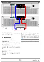
The wiring of terminal „Share“, which is required for Share bus
operation, is explained in section „5.8. Terminal „Share““. Also
see figure 14.
Note
If remote sense is going to be used, it is recommended only
to connect the „Sense“ input of the main unit that determines
the system voltage.
Attention!
This is a purely analog connection. No totals formation
of actual values on any of the units.
Attention!
Parallel connection with units different to 3U series, which
also feature a Share bus, is not allowed!


