51
Operating Guide
PSI 8000 3U HS PV Series
EN
Date: 20-05-2016
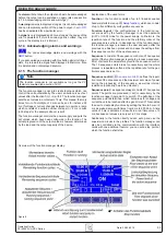
Set values are submitted
Alternatively to the direct adjustment of set values you can
choose to set the set values only after submitting them with
the
RETURN
panel“ for details. The set values can still be changed with the
rotary knobs, but are not set to the output as long as they’re
not submitted. While the set value is unchanged, only its unit
is displayed inverted. If the set value is changed it is also dis-
played inverted.
The
SELECT
keys switch from current adjustment to power
adjustment for the right rotary knob. The chosen set values are
not submitted to and set by the power supply until then.
Pressing the
RETURN
button submits the set values.
Pressing the
ESC
button discards the new set values
and the old set values are displayed again.
Note
The adjustment of the resistance set value is only accessible
after the optional „internal resistance control“ is unlocked
Note
The resistance set value is adjustable from 0Ω up to
20* U
nom
÷ I
nom
. Means, for example, at a device with U
nom
=
1000 V and I
nom
= 30 A it can be adjusted to a maximum of
666.6Ω.
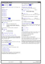
Using predefined set values
A table of up to 4 sets of set values is accessible in the menu
Preset List
(see
„7.2. Predefining preset lists“
). The left knob
selects the preset list and with the
RETURN
button the set is
submitted or discarded with the
ESC
button.
The chosen set is still 1. After the
RETURN
button
is pressed, the set values of set 3 are submitted to the power
supply. The display then shows the new set values of set
3
.
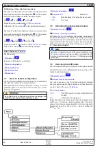
The
ORY
button can be used to jump straight to the
menu page where the preset lists are defined and there they‘re
edited and submitted with
RETURN
as usual.
Step widths for set value adjustment
Voltage
Current
Nom. val Coarse Fine
Nom. val Coarse Fine
600 V
5 V
0.1 V
30 A
0.2 A
10 mA
1000 V
10 V
1 V
70 A
0.5 A
10 mA
1500 V
10 V
1 V
Power
Resistance
Nom. val Coarse Fine
Nom. val
Coarse Fine
10 kW
0.10 kW 0.01 kW
171.4/666.7 Ω 1 Ω
0.1 Ω
15 kW
0.10 kW 0.01 kW
1.000 kΩ
10 Ω
1 Ω
Note
The resolution of the set value adjustment in some cases is,
depending on the nominal values, higher than the one of the
output voltage. Thus it can happen that the output voltage
only changes every 2 or 3 steps
6.7 Switching the button panel
The button
PAGE
is used to switch to another button
panel. The new button assignments of the other panel allow the
user to lock the control panel, switch to the function manager
or set the location mode.
6.8 Locking the control panel
The button „Lock button panel“ locks all buttons, except
itself, and the rotary knobs. The unit is now locked from manual
access, so that no set value can be changed or no menu is
accessible. The locking mode can be set up in the menu. The
control panel can be either completely inactive or it can exclude
the
OFF
button (the unit is then locked but can be switched off
and on by the
OFF
button). See also „Control panel lock“ in
section
„7.4. Configuring the control panel“
.
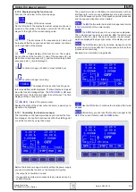
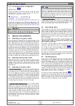
After the control panel was locked it changes to this
icon. The button can be used to unlock the control panel again,
if button
is pressed within 2 s.
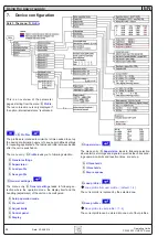
6.9 Control locations
With the button
EXT
the user enables the remote control
of the unit via a digital or analog interface card and deactivates
the
local
mode.
With the hand button the user sets the unit into strict
local
mode, so that it is only manually controllable. Access
by any interface, analog or digital, is then blocked.
6.10 Switching to the function manager
The
SEQ
button switches the display to the function
manager mode.
Switching to the function manager is only possible while the
unit is in standby (output = off). The set values of voltage and
current are set to 0 V and 0 A. For details about the function
manager see section „6.15. The function manager“.
Using the power supply


