Page 10 of 24 M6493 Issue 10.3
7. PRODUCT OPERATION.
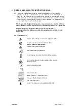
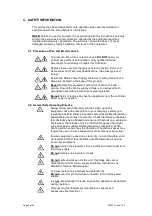
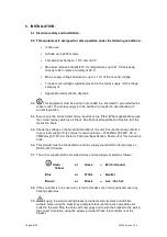
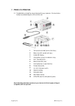
7.1. The MC810B controller has been designed for easy operation. The illustrations
below show detailed layouts of this control unit.
1
Instruction book label (refer to this book).
2
Mains input IEC socket with fuses.
3
3 digit LED display
4
Orange Neon power on indication lamp.
5
Exit / Standby button
6
Mains Output IEC plug.
7
Earth protective conduct terminal.
8
Temperature probe
9
On / Off, I/O power switch.
10
Retort rod clamp
11
Data plate label
12
Wall bracket clamp.
13
5 Pin DIN socket for temperature probe.
Check the data plate label and ensure your mains electrical supply voltage is
compatible with this product.


