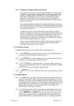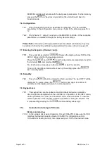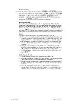
Page 17 of 24 M6493 Issue 10.3
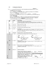
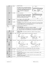
*ATM
NON;
ABS;
REL
Alarm threshold management.
NON: all temperature alarms are inhibited
(the following parameter will be
SB)
.
ABS: the value programmed in
ALM
and
AHA
represent the real alarm thresholds.
REL: the value programmed in
ALR
and
AHR
are alarm differentials reerreed to
1SP
and
1SP+1HY
*A
T
M
=
ABS
ALA
-50° …AHA
Low temperature alarm threshold.
AHA
ALA +150°
High temperature alarm threshold.
*A
M
T
=
R
E
L
ALR
-12..0°
Low temperature alarm differential.
With AHR=0 the high temperature is excluded.
AHR
0…12.0°
High temperature alarmdifferential.
With AHR=0 the high temperature is excluded.
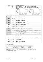
*ATD
0…120 min
Delay before alarm temperature warning.
*SB
NO / YES
Stand-by button enabling.
*INP
0mA/4mA
Sensor input selection (see table of input specifications).
*RLO
-19.9…RHI
Maximum range values.
RLO
takes the maximum value measured by the transmitter
(i.e. the value matching 1V, 20mA)
*RHI
RLO..99.9
Maximum range vlue RHI takes the maximum value measured by the transmitter (i.e.
the value matching 1V, 20mA).
*OS1
-12.5..+12.5
Probe T1 offset.
*TLD
1…30min
Delay for minimum temperature (TLO) and maximum temperature (THI) logging.
*SIM
0…100
Display slowdown
*ADR
1…255
Address for PC communication.
Input Specification
Input
Range [Measurement Accuracy]
SCL=1°C
SCL=2°C
SCF=°F
PT100
-50/-19.9÷99.9/150°C
[<±0.3°C]
-100÷850°C
[<±1°C(-50÷850°),±2°C]
-150÷999°F
[<±2°F(-60÷999°),±4°F]
NOTE:
Certain times are not used on the MC810B configuration and should be left set at the
manufactured default setting.


