background image

4

Installation

Leveling

It is extremely important that the unit is level for 
maximum protection.

If it is not:

  •  Doors and/or drawers will not work properly.
  •  Uneven sized cubes will be formed. Ice 

production will be reduced and water spilling 
into the storage area can occur, causing 
the ice in the bin to melt prematurely. 

See 

Figure1.

Remember, floors surrounding a drain have a 
tendency to slope toward the drain.


IMPORTANT

Properly aligned, the door should be 1/8” below 
the top of the unit’s cabinet, NOT flush with the 
top. 

See Figure 4.

Adjusting Door

Checking Door Alignmemt

The unit’s door is aligned at the foctory before 
shipment. However, its alignment could have been 
disturbed during shipment or during door panel 
installation.


1

  Compare the top edge of the door to the top 

edge of the cabinet.


2

  If the door edge is 1/8 inch below and 

parallel to the top of the cabinet, it is adjusted 
correctly. If it is not, note whether the side 
oposite the hinge needs to be moved UP or 
DOWN, and use the following procedure:

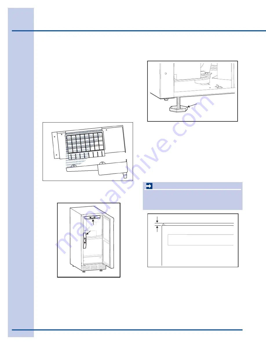
  1.  Use a level to check the unit from front to 

back and from side to side. 

See Figure 2.

Figure 1

CHECK

LEVEL

Figure 2

TURN FOOT TO ADJUST

Figure 3

  2.  If the unit is not level, adjust the feet on the 

corner as necessary. 

See Figure 3.

 Rotating 

the feet clockwise raises the unit.

  3.  Check after each adjustment. Repeat the 

previous steps as necessary until the unit is 
level.

1/8”

Figure 4

Summary of Contents for E15IM60GPS

Page 1: ...5995504544 January 2008 Under the Counter Ice Maker Service Manual Models EI15IM55GS E15IM60GSS and E15IM60GPS ...

Page 2: ...ffthegassupply Turnoffthewatersupply 3 Never interfere with the proper operation of any safety device 4 USE ONLY REPLACEMENT PARTS CATALOGED FOR THIS APPLIANCE SUBSTITUTIONS MAY DEFEAT COMPLIANCE WITH SAFETY STANDARDS SET FOR HOME APPLIANCES 5 GROUNDING The standard color coding for safety ground wires is GREEN or GREEN with YELLOW STRIPES Ground leads are not to be used as current carrying conduc...

Page 3: ...p Maintenance 20 Refrigerant Leaks 21 Leak Detection 21 HFC 124a CFC 12 Pressure Temperature Chart 22 Inhalation Toxicity 23 Cardiac Sensitization 23 Table of contents Spills and leaks 23 Skin and Eye Contact 23 Combustibility of HFC 134a 24 Leak Testing 24 Bulk Delivery and Storage 24 Filling and Charging Operations 24 Refrigerant Recovery Systems 24 Thermal Decomposition 24 Ice Cube Thickness Ad...

Page 4: ...ned at the foctory before shipment However its alignment could have been disturbed during shipment or during door panel installation 1 Compare the top edge of the door to the top edge of the cabinet 2 If the door edge is 1 8 inch below and parallel to the top of the cabinet it is adjusted correctly If it is not note whether the side oposite the hinge needs to be moved UP or DOWN and use the follow...

Page 5: ...t to assure that it is firmly in contact with the cabinet 2 If the door is properly aligned no further adjustment is necessary If it is not use the following procedure Notch Slotted Mounting Holes Raise Outside Door Edge Lower Outside Door Edge ULIN_0297_A Angled Edge Towards Center of Door Slotted Mounting Holes Raise Outside Door Edge Lower Outside Door Edge ULIN_0311_A 2115WC 2115WCOL 2175WC 21...

Page 6: ...level horizontally If both drawers are properly aligned no further adjustment is necessary If either drawer is not aligned carefully follow instructions to remove that drawer make the necessary adjustment and re install the drawer ULIN_0293_A ULIN_0104_A 7 Adjust Drawer Aligned Side to Side Aligned Front to Back Aligned Top to Bottom ULIN_0312_A Figure 10 2 Align door squarely with cabinet Make su...

Page 7: ... the keypad Ice Maker Off Mode not available Force Harvest This mode can be used to force ice to harvest from the mold To enter this mode hols the LIGHT key and press the UP arrow three times The unit will initiate an ice harvest There is no audible tone when entering this mode Forced Defrost This will allow the unit to defrost quickly For R and WC units this is just an off cycle For units with ho...

Page 8: ...should turn off with the door switch or not At the 0 reading the light should be off with the door closed and on with the door open At the 1 reading the light always stays on 8 Display toggle status 0 or 1 This will tell if the display should turn off with the door switch or not At the 0 reading the light should be off with the door closed and on with the door open At the 1 reading the light alway...

Page 9: ...mp Ref Valve Ref Bypass Valve Compressor Fan t h g i L 7 7 1 3 6 V E B 5 7 1 2 2275DWRWS 85186 Cond Fan Bottom Light Compressor Top Light Bottom Valve Top Valve 61 2175R 120V 62 2175WC 120V 63 2175BEV 120V 64 CO2175F 120V 65 2175RF 120V 66 CO2175DWR 120V 67 CLR2160 120V 68 CLRCO2175 120V 70 2175DWR 120V 71 2115R 120V 72 2115WC 120V 73 2115R 220V 74 2115WC 220V 75 2175R 220V 76 2175WC 220V 77 2175B...

Page 10: ...mode d l o H t s o r f e D r o t a r e g i r f e R d e c r o F 5 1 Audible alert when entering this mode d l o H t n e m t s u j d A s s e n k c i h T e c I 6 1 Use WARMER COLDER to scroll d l o H d l o H e d o M e c i f f O n w o d t u h S y r a r o p m e T 7 1 Icemaker will automatically turn back on in three hours s u t a t S y a l e R 8 1 Relay Number with 1 or 0 to indicate on or off Relay 3 ...

Page 11: ...ose the correct option To view the thermistor temperature hold the WARMER key for approximately five seconds until the F flashes Release and the display will show the corrected refrigerator temperature For Wine Cooler models the display will cycle through all three zones These temperatures are approximate and calibrated for a cabinet in normal ambient temperatures with some product load Checking a...

Page 12: ...wed perform Option 12 to clear the errors from memory 4 Defrost Information Displays the number of defrosts that have occured in the past 24 hours 5 Compressor runtime based on last cycle This will show the number of minutes the compressor has run in the prior cycle or current cycle if the compressor was running when Service Mode was entered 6 Defrost length adjust min 99 minutes The length of the...

Page 13: ...g i L r o f n o t h g i l r o i r e t n i n r u t l l i w n o t t u b t h g i l g n i s s e r P f f o n r u t l l i w t i n e h t s r u o h 4 g n i t s i L e d o M e c i v r e S s e d o C r o r r E s t n e m g e s D E L l l a t h g i L 1 0 n e p o r o t s i m r e h T 1 E s u t a t S r o t s i m r e h T 2 0 d e t r o h s r o t s i m r e h T 2 E g o L r o r r E 3 0 s e t u n i m 0 2 n a h t r e g n ...

Page 14: ...esistance at 77 F 5 000 Ohms 5 Operating range is 180 000 to 550 Ohms Resistance goes down as temperature increases Type 2 does not need to be calibrated and can be changed without changing other wires or board Refrigeration System Diagnosis Guide System Condition Suction Pressure Suction Line Compressor Discharge Condenser Capillary Tube Evaporator Wattage Normal Normal Slightly below room temper...

Page 15: ...em using the recommended procedure described under Evacuating and Recharging 10 Reassemble unit Evacuating and Recharging CAUTION Check the serial plate for the correct refrigerant type It is extremely important to verify the type of refrigerant in the system before starting any sealed system repairs With the possible exception of the vacuum pump all service equipment that comes in contact with R ...

Page 16: ... shaking the compressor this will allow the moisture to come to the top of the oil faster so the vacuum pump can remove the moisture from the system CAUTION If high vacuum equipment is used just crack both manifold valves for a few minutes and then open slowly for the two full turns counterclockwise This will prevent the compressor oil from foaming and being drawn into the vacuum pump Evacuating S...

Page 17: ...t charging cylinder scale to pressure indicated on cylinder pressure gauge 4 Observe refrigerant level in sight glass Subtract amount to be charged into system and note shut off point 5 Open charging cylinder valve slowly and allow proper charge to enter system 6 As soon as refrigerant in sight glass has gone down to predetermined level close charging cylinder valve 7 Allow system to sit for five ...

Page 18: ...ation Hot Tube Evaporator Condenser Compressor 2 Stage Vacuum Pump Heated Charging Cylinder Process Tube Adapters Filter Drier Pressure Gauge Compound Gauge Gauge Manifold T Fitting Evacuating and Recharging Connections ...

Page 19: ...ist of the same basic components being utilized in the R 12 systems There is a 10 to 15 discharge pressure increase using R 134a with a 5 to 10 decrease in suction pressure when compared to the same product with an R 12 system operating at 90 F 32 C ambient temperature conditions Lower suction pressures result from the lower density of R 134a refrigerant which effects refrigerant flow rate R 134a ...

Page 20: ...uum than a single stage because the exhaust from the first pumping stage is discharged into the second pumping stage This means the second stage begins pumping at a lower pressure so a lower ultimate vacuum can be achieved See 2 Stage Vacuum Pump Figure E3 VACUUM CHART Vacuum Inches Hg Microns Boiling Point of Water F 28 940 25000 77 9 29 530 10000 52 0 29 832 4600 32 0 29 882 1000 1 0 29 901 500 ...

Page 21: ...faster so the vacuum pump can remove the moisture from the system Electrolux Home products does not approve the use of the Sweep Charge for sealed system repair This method of servicing sealed systems we know is often used to repair products in the field The Sweep Charge does not adequately remove the moisture from the oil in the compressor In a R 134a system you will need to replaced the compress...

Page 22: ...5 108 3 15 26 1 0 0 2 4 100 37 8 123 6 117 2 10 23 3 1 9 4 5 105 40 6 134 3 126 6 5 20 6 4 1 6 7 110 43 3 145 6 136 4 0 17 8 6 5 9 2 115 46 1 157 6 146 8 5 15 0 9 1 11 8 120 48 9 170 3 157 7 10 12 2 12 0 14 6 125 51 7 183 6 169 1 15 9 4 15 0 17 7 130 54 4 197 6 181 0 20 6 7 18 4 21 0 135 57 2 212 4 193 5 25 3 9 22 1 24 6 140 60 0 227 9 206 6 30 1 1 26 1 28 5 145 62 8 244 3 220 3 35 1 7 30 4 32 6 1...

Page 23: ...diac arrest If the person is having difficulty breathing administer oxygen If breathing has stopped give artificial respiration Spills or Leaks If a large release of vapor occurs such as from a large spill or leak the vapors may concentrate near the floor or low spots and displace the oxygen available for breathing causing suffocation Evacuate everyone until the area has been ventilated Use blower...

Page 24: ... either tanks or HFC 134a supply system usually prevent this Tank pressures should be monitored routinely Air lines should never be connected to storage tanks Filling and Charging Operations Before evacuating cylinders or refrigeration equipment any remaining refrigerant should be removed by recovery system Vacuum pump discharge lines should be free of restrictions that could increase discharge pr...

Page 25: ...justment mode 4 Remove all ice from the storage bin 5 Ice cubes in any given batch will vary so it is necessary to choose cubes from the sample area Figure 25 for comparison when making adjustments If further adjustments are desired repeat steps 1 through 4 DIMPLES ICE BRIDGE ICE001 Figure 25 The ice cube thickness control is factory set for best overall performance The factory setting is designed...

Page 26: ...fications DANGER Electrocution can cause death or serious injury Burns from hot or cold surfaces can cause serious injury Take precautions when servicing this unit Disconnect the power source Do not stand in standing water when working around electrical appliances Make sure the surfaces you touch are not hot or frozen Do not touch a bare circuit board unless you are wearing an anti static wriststr...

Page 27: ...LY R5 WATER CIRCULATION PUMP R4 HOT GAS BYPASS VALVE R1 CONDENSER FAN CONDENSER R3 COMPRESSOR RELAY R1 R3 R4 R5 FUNCTION FAN ON ON OFF OFF OFF ON ON OFF OFF OFF OFF ON OFF ON OFF ON ON OFF OFF ON OFF OFF COMP CIRC PUMP HOT GAS WATER IN Mode 1 Ice Making Mode 2 Ice Harvest Mode 3 Off Mode 4 Cleaning Mode 5 Water Fill Initial Start Up Normal Start Up lasts 3 minutes Note R2 R6 and R7 not used ...

Page 28: ...ase the ON OFF key for the third time The display will cycle through a series of numbers to tell which relays are energized For example if the unit was in ice making mode the display would show 11 20 31 40 51 60 70 The first number is the relay number In the second number 1 means on and 0 means off The relay information can be found in the Control Section Each relay can also be turned on and off i...

Page 29: ... water flow over the mold to see if excess water is being splashed out of the trough This could be the result of improper leveling Ice does not release from evaporator This could be caused by improper leveling or the unit is in need of cleaning Poor ice quality This can be caused by poor incoming water quality The CLR2160 is designed to produce clear ice in most water however abnormal water condit...

Page 30: ...duction Rates NOTE These characteristics will vary depending on operating conditions condenser cleanliness installation and application ULIN_0262_A Ambient Temp Water Temp F Approximate Ice Production lbs day 50 50 60 60 50 60 70 50 58 80 50 54 90 70 47 100 70 40 ...

Page 31: ... drop per 48 of run 1 4 per foot Drain line does not create traps or created traps are vented Figure 2 Figure 2 See Figure 3 for a typical gravity drain installation Figure 3 If using a gravity drain 1 Attach the 5 8 ID drain connection on the back of the unit to a 5 8 OD rigid tube using a worm clamp 2 Attach the other end of the rigid tube to your 5 8 ID drain line with a worm clamp 3 Insulate t...

Page 32: ...cept the discharge tube during testing Failure to follow this warning could result in serious personal injury or death 4 Check that the clamps and hose connections are tight at the following areas Figure 8 Discharge tube A Drain tube B Vent tube C Figure 8 5 Place a suitable container beneath the pump s discharge tube The bucket must be able to hold a minimum of one gallon 6 Plug the ice maker pow...

Page 33: ...er supply location 1 4 O D soft copper tubing 10 or more depending on drain location 5 8 I D braid reinforced PVC drain tubing 3 11 16 to 1 1 4 Clamp range worm drive hose clamps 1 Brass garden hose fitting supplied with product 1 Nylon barbed coupling for 5 8 ID hose 1 5 8 to 7 8 adapter Depending on your model your unit may have been packaged with these items If you need to order these items ple...

Page 34: ...ng The rubber washer provides an adequate seal Other materials could cause blockage of the valve The copper water line should now be clamped to the rear of the unit to prevent rotation when sliding in Remove the clamp from the unit slide the tube into it and reattach using the 1 4 nut driver as shown Figures 11 and 12 7 Plug in the unit and put the unit into OFF mode by holding the power key for 1...

Page 35: ... of water into the ice bin and check all drain connections for leaks During this time also ensure that the water flows from the bin If the water does not flow from the bin there may be a problem with the drain connection such as kinks or improper slope If your unit has a drain pump an indicator of P1 on the display will alert to a slow or clogged drain If any problems are found retrace the drain c...

Page 36: ...ce the overflow tube after all the water has been drained from the reservoir 5 Hold down the ON OFF key and press LIGHT three times to enter cleaning mode 6 When water begins to flow over the evaporator approximately three minutes add one packet of U Line Ice Machine Cleaner to the reservoir 7 Reinstall inside front cover 8 When the self cleaning process stops approximately 45 minutes it may be de...

Page 37: ...ATER PUMP ASSY 27 55 DRAIN INSTALLATION KIT U CLRDRAINKIT not shown ULIN_S_0047_A 7 6 3 2 4 8 11 5 EI151M55GS Parts Section Model CLR2160 47 CLR2160 Figure 21 8 Parts Section Item Description Figure Page 2 INTERIOR CLR2160 24 51 3 HINGE COMP 25 52 4 DOOR COMPONENTS 25 52 5 BASE ASSY CLR2160 26 54 6 CONTROL COMPONENTS 22 48 7 BACK PANEL CLR2160 23 50 8 GRILLE ASSY 25 52 11 WASTE WATER PUMP ASSY 27 ...

Page 38: ... BOARD ASSEMBLY 68072 S 3 SWITCH JUMPER included with 68072 S 68080 4 CIRCUIT BOARD SUPPORTS included with 68072 S 41992 5 CIRCUIT BOARD SUPPORT included with 68072 S 41993 6 LIQUID LINE THERMISTOR quick connect black 68076 7 BASEPLATE LINER 26086 8 DISPLAY ASSY ECHELON 68074 9 DISPLAY GLASS ECHELON CONTROL 68059 01 10 HOUSING DISPLAY 26089 11 SCR 8 18X 75 PLASTITE PAN 42162 ...

Page 39: ... S 2819 8 CONDENSER ASSEMBLY 2269 S 9 WIRE ASSEMBLY PUMP TO POWER CORD 2892 02 ULIN_S_0085c_A 5 4 3 1 2 9 6 7 8 50 Model CLR2160 Figure 23 Item Description Part Number 1 BACK PANEL 11964 02 2 BACK PANEL SCREWS 41342 3 SOLID HOLE COVER 42125 4 PERFORATED HOLE COVER N A 5 BLACK BUSHING 41955 6 DRYER included with 2269 S 2850 7 PROCESS TUBE included with 2269 S 2819 8 CONDENSER ASSEMBLY 2269 S 9 WIRE...

Page 40: ...RECEPTACLE 11812 S 9 CIRCULATION PUMP ASSEMBLY 31613 S 10 ICE SCOOP 31614 11 SCREWS included with 31613 S 41981 Model CLR2160 51 Figure 24 ULIN_S_0075_A 10 4 8 2 5 6 7 1 9 3 11 Item Description Part Number 1 STAND PIPE 31619 2 FRONT COVER 11868 3 WELL NUT included with 31613 S 41979 4 PRE FORMED WHITE TUBE 31615 S 5 CIRCULATION PUMP COVER 11893 6 ICE SCOOP HANGER 42011 7 WATER TROUGH WITH DRAIN TU...

Page 41: ...95 06 12095 05 7 PIVOT PLATE 11901 1 BLK S 11901 1 BLK S 11994 BLK S 8 SCREWS included with 11901 1 BLK S 42161 ZP 42161 ZP 42161 ZP 9 HINGE ASSEMBLY TOP 11898 S BLK 11898 S KIT 11995 S SS 10 HINGE ASSEMBLY BOTTOM 11899 S BLK 11899 S KIT 11996 S SS 11 DOOR CLOSER ASSEMBLY 31673 S 31673 S 31673 S 12 HINGE SCREWS included with hinge assemblies 42101 BLK 42101 ZP 42101 SS 13 PIVOT POST included with ...

Page 42: ...42 Parts Information 54 Model CLR2160 Figure 26 ULIN_S_0064b_A 5 2 3 4 1 6 7 10 11 8 9 12 13 14 15 16 17 18 ...

Page 43: ...2 1 S 17 FOOT LEVELER 1 4 20 41319 18 POWER CORD 2949 Item Description Part Number 18 WASTE WATER PUMP KIT P 60 Model CLR2160 55 Figure 27 Figure 26 Figure 27 ULIN P60 00_A 18 Item Description Part Number 1 COMPRESSOR EMY70HER 70081 S 2 PROCESS TUBE included with 70081 S 2819 3 DRYER included with 70081 S 2693 4 GROMMET included with 70081 S 31021 5 OVERLOAD included with 70081 S 71027 6 RELAY inc...

Page 44: ... 8 ID included with 2276 S 31410 9 ARMAFLEX 1 5 8 ID included with 2276 S 31636 1 3 4 5 9 7 8 6 2 ULIN_S_0077_A 56 Model CLR2160 Figure 28 Item Description Part Number 1 EVAPORATOR ASSEMBLY 2276 S 2 HEAT EXCHANGER included with 2276 S 2725 S 3 PROCESS TUBE included with 2276 S 2819 4 BYPASS TUBE included with 2276 S 2836 5 SUCTION TUBE included with 2276 S 2837 6 DRYER included with 2276 S 2850 7 ...

Page 45: ...lication of heavy usage Heavy usage or high ambient temperature will cause a unit to frost up Water is leaking out of the unit Have you checked the water connection to the unit The warranty does not cover installation adjustments No ice or not enough ice All models Are you aware of the factory specifications for ice production Is the door or drawers sealing properly Has the ice maker been turned o...

Page 46: ... minutes a service call will be required My ice does not come out in a perfect cube shape When the ice is made a small hole or dimple will appear on the front or top of the cube Increasing or decreasing the time of the freeze cycle will adjust the size of the dimple The cubes do not fall into the bin as individual cubes This is normal You can use the scoop to break the cubes apart Not enough ice i...

Page 47: ......
Reviews: