background image

Contents

Technical Handbook

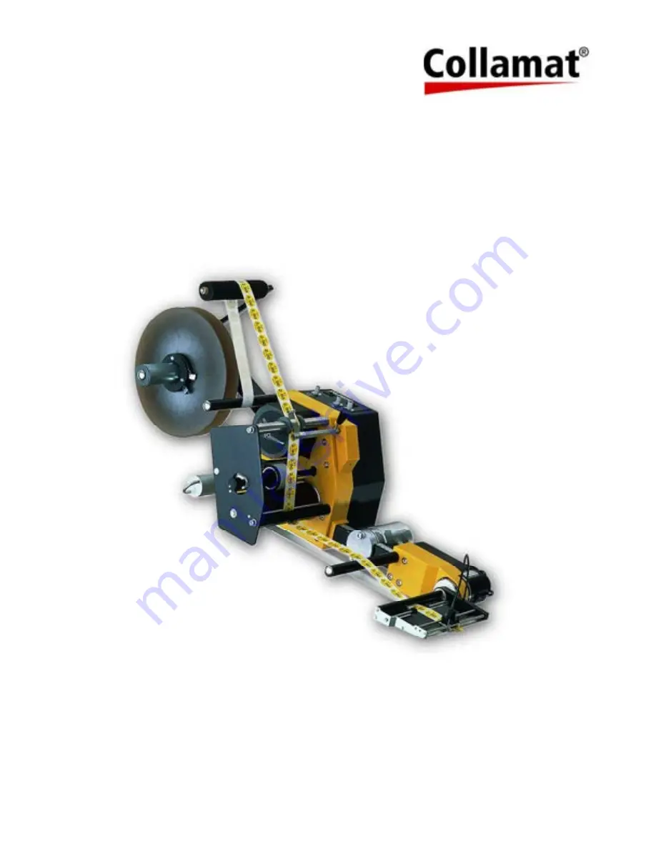
Collamat C4300- / C7300- Series

Doc-ID: TH-C4300-C7300-EN
Release: 1.00/01/2013

This manual is a translated English version. The only mandatory
Technical Handbook for this product is the German version – signed
as the Original-/Reference-Version.

These Operating Instructions and the Technical Handbook have to be read before start up, and before any work
are done on the machine.

Summary of Contents for C4300 Series

Page 1: ...013 This manual is a translated English version The only mandatory Technical Handbook for this product is the German version signed as the Original Reference Version These Operating Instructions and t...

Page 2: ...rence Version SD 28 01 2013 16 49 Etikettiersysteme Bodenmattstrasse 34 4153 Reinach BL Switzerland Tel 41 0 61 756 28 28 Fax 41 0 61 756 29 29 E mail info collamat ch Internet www collamat ch Produce...

Page 3: ...5 Industrial safety and special hazards 15 2 6 Conduct in emergencies and accidents 19 2 7 Safety equipment 19 2 8 Assure against power on 20 3 Technical specifications 21 3 1 Dimensions of Collamat...

Page 4: ...ak 44 7 3 2 Rewinder clutch adjustment 45 7 3 3 Modular rail 45 7 3 4 Pressure roller 46 7 3 5 Adapter tilt angle 46 7 3 6 Adapter front pressure roller 47 7 3 7 Adapter optical label scanner 47 7 3 8...

Page 5: ...1 8 3 Applicator Adapter 62 8 3 1 Applicator Adapter Types 62 8 3 2 Connection FUTURE bus 62 8 3 3 Connections applicator terminals 63 8 3 4 Connection Applicator PE 64 8 3 5 Label scanner explanation...

Page 6: ...Contents 6 12 1 Abbreviations general 76 12 2 Signal names 76 12 3 Terms explanations 76 13 INDEX 79 14 APPENDIXES 81...

Page 7: ...read carefully before all work They are part of the product and must be kept near to the machine and accessible to the personnel at all times If the machine is passed on to third parties the operatin...

Page 8: ...situation which may cause death or serious injury if it is not avoided WARNING indicates a possibly dangerous situation which may cause death or serious injury if it is not avoided ATTENTION indicates...

Page 9: ...e manufacturer warrants the functionality of the process methods and the specified performance parameters The term of warranty begins at the time of delivery of the machine to the customer Wearing par...

Page 10: ...onditions of warranty The warranty conditions are contained as a separate document in the sales documents 1 7 Customer service Our customer service is available to provide technical information Inform...

Page 11: ...els The machine operates fully automatically The working area of the machine should be protected against unauthorized access WARNING Danger due to incorrect use Any use which exceeds the intended use...

Page 12: ...tructions for the operation of the machine at the particular site During the entire period of operation of the machine examine whether the operating regulations which he has produced conform to the cu...

Page 13: ...lectricians are in a position to carry out work on electrical equipment and to independently recognize possible hazards due to their specialist training experience and knowledge of the relevant standa...

Page 14: ...equipment and wear it while working In addition signs in the work area concerning personal protective equipment must be observed To be worn For all work the following must be worn Industrial safety c...

Page 15: ...ns with danger of death due to electrical current If the safety information is not observed there is danger of death or serious injury The work should only be performed by a qualified electrician WARN...

Page 16: ...ment carried out by qualified electricians Switch off the power before undertaking any work on electrical equipment Check that no voltage is present Before carrying out regular maintenance cleaning an...

Page 17: ...danger area Switch off the power supply and secure against switching on again Wait until moving parts have come to a standstill Wait for the self acting reduction and or discharge of residual energy...

Page 18: ...adjustment and maintenance work or remedying faults personal protective equipment should be worn Dirt and scattered objects BEWARE Danger of tripping due to dirt and scattered objects Dirt and scatter...

Page 19: ...r access routes for emergency vehicles 2 7 Safety equipment WARNING Danger of death due to non functioning safety devices Safety devices ensure that the operation is as safe as possible Even if work p...

Page 20: ...re Check the area of danger before switching on the machine Protection against unauthorized power on 1 Switch off mains power 2 If possible lock mains switch with a padlock and mark the switch with an...

Page 21: ...C7300 Series C4310 P C7310 P 1 95 mm 2 305 mm 3 965 1315 mm 4 518 648 mm C4320 P C 7320 P 1 160mm 2 350 mm 3 965 1315 mm 4 518 648 mm for P R right version see picture for P L left version Measuremen...

Page 22: ...ing speed s 4 speed 25m min s 7 speed 50m min ww x Width max paper width ww 95mm ww 160mm x 3 low cost version D optional Direction L Left R Right Labeling direction Left Collamat version Right Collam...

Page 23: ...only use original good sensors from Collamat AG or ask a skilled labor how to connect another product brand to your labeler Future Bus standard The 14 pin connector left and right near the main conne...

Page 24: ...The paper break can optionally be configured to act as paper break sensor This sensor checks the paper path In case of empty paper roll OOL Out Of Label or in case of a paper break no paper label betw...

Page 25: ...power connections C4300 C7300 Explanation IP protection 1 st digit Protection against touching and against intrusion of foreign particle Description Value Unit Protection against mass foreign particle...

Page 26: ...vel max dB A 3 6 Performance values Description Value Unit max labeling speed s 25 50 m min max predispensing value 100 mm Stop tollerance 0 5 mm max paper width 95 160 mm min paper width 10 mm min la...

Page 27: ...g Description Clamp unit project specific 3 9 Identification plate Description Value Unit Type Cs3ww D Year 10 2012 Voltage 115 230 VAC Fuse 5 0 2 5 AT C4300 C7300 138 198 VA S N Serial Number 00001 s...

Page 28: ...on Side labeling set optional 1 Unwinder dancer holding disc 2 Unwinder disc 3 Rewinder holding disc 4 Stabilization set for unwinder 1 Dancer unwinder unit 3 Traction unit 5 Modular rail 30x30 7 Appl...

Page 29: ...on make Applicator type Description Applicator fix FXA Fixed dispensing edge Applicator spring loaded SLA Spring loaded disp edge Air Vacuum Applicator AVA Suction plate piston s Magnet Flap Applicato...

Page 30: ...er around the dispensing edge A controlled stepper motor is fulfilling this job The backing paper is then guided to the rewinder unit where the waste of the paper web backing paper is spooling winding...

Page 31: ...placing the straps take care that individual components are not unduly loaded BEWARE Damage due to incorrect transport Incorrect transport may cause considerable damage Therefore When unloading the p...

Page 32: ...laint INFORMATION Complain of all faults as soon as they are apparent Only in this way can claims for com pensation be made within the applicable periods 5 4 Transport Transport of the Collamat C4300...

Page 33: ...erials are valuable raw materials and in many cases can be re used or processed and recycled Therefore Dispose of packaging materials in an environmentally friendly manner Observe local regulations fo...

Page 34: ...hat all components are in the correct location and are correctly seated Install all fixing elements correctly Observe the correct screw tightening torques Before switching on ensure that all covers an...

Page 35: ...d on again without authorization This causes danger of death for those in the danger area Therefore Before starting work disconnect all power sup plies and secure them against being switched on again...

Page 36: ...space for movement and the escape routes the regional or national regulations for the installation site must be observed Stability A Collamat C4300 C7300 mounted on a movable stand adjustable or fix...

Page 37: ...plicator cable flat ribbon 20 pin w connector optional Slide mounting clamp to the modular rail if the mounting point for the labeling unit is the modular rail Connecting the applicator unit to the mo...

Page 38: ...s Standards References According to the machine directives 2006 42 EG a machine is a not complete machine if the unit is not able to fulfill all functions the unit has been built for This are by defau...

Page 39: ...ll a pressure air line if required Make sure the line is save tripping hazards INFORMATION The safety equipment optional makes sure no labeling sequence can be triggered without explicit permission Th...

Page 40: ...lose the cover 2 The power outlet plug is designated to connect Collamat C4300 C7300 peripherals ONLY 3 Plug in power cord line cord into a local power outlet The power outlet has to be secured with 1...

Page 41: ...g a unit is often the cause of an unstable unit Therefore the following points have to be observed while working on the wiring Separate installation of control and power lines Use shielded cables Grou...

Page 42: ...y All operating steps must be performed according to these operating instructions Before starting work ensure that all covers and safety devices are correctly installed and function correctly Safety d...

Page 43: ...per web Adjust the declination of the dispensing edge and the applicator unit Adjust the pressure roller applicator Align the label sensor receiver head Power on the Collamat C4300 C7300 mains switch...

Page 44: ...winder clamp Press down the pressure roller turning the button on the pressure roller axle Adjust the unwinder disc s and the paper guide rings slide to the outer edge of the paper web Labeler Version...

Page 45: ...ch has to be done as following Remove the rewinder core 1 after unscrewing the M5 screw 3 Adjust M8 screw 2 corresponding screw in firmer clutch screw out weaker clutch 7 3 3 Modular rail Vertical adj...

Page 46: ...ut 1 see illustration using special hexagon socket spanner included in supply with two rotations Push adapter in direction of arrow 2 and turn into the desired position on ring 3 Tighten nut 1 The str...

Page 47: ...nside the dispensing edge The manipulation lengthwise is not necessary as this is done electronically 1 Receiver head 2 Transmitter light tube inside dispensing edge 3 Marking on receiver head Setting...

Page 48: ...er 2000mm forward feeding after start signal and the ERR output will be set for a short time if the scanner does not see a gap For transparent labels clear view use a mechanical or capacitive label se...

Page 49: ...k force Released dancer arm no paper is pulling on the dancer arm the dancer is in the waiting position maximum brake force the unwinder is stopped by the break Dancer arm forced down by the paper web...

Page 50: ...uct or label change The meaning of the different adjusting parameter will be explained in a separate chapter Important adjustments POWER ON OFF main power switch of the labeler FEED FEED key SPEED Dis...

Page 51: ...ge of the label on the dispensing edge allowing to stop the labels always on the same stop position on the dispensing edge The potentiometer LABEL SCANNER on the operator plate is used to control the...

Page 52: ...wird kann dies zu Fehlverhalten des Etikettierers f hren 7 5 3 Labeling parameter label scanner LABEL SCANNER Adjust the label sensor sender current The C4300 C7300 standard label scanner is an optic...

Page 53: ...FF state only Jumpers on the main board PCB There are several jumpers on the main board Polarity IFEED normal inverse Turning direction of stepper motor right left Test function 1 3 or off See all the...

Page 54: ...ion 1 2 Test function 2 activated Jumper 1 und 2 Position 1 2 Test function 3 activated 7 7 Placing into operation Step by Step procedure to place the unit into operation Mount unit with paper unwinde...

Page 55: ...for a clean and organized mounting area A messy place is always a place of danger cause of accident Open collector und power connections have to be current limited according to the specified max value...

Page 56: ...ted GND level If the good scanner tries to start the labeler anyway the error output ERR ERR will be set short error pulse RDY signal GND ground level FEED output FEED This output stays active ground...

Page 57: ...licator in the back of the modular rail 8 1 4 Connection FUTURE BUS Function Pin assignment The FUTURE BUS connector X101 and X102 will be used to connect peripheral devices to the labeler via flat ca...

Page 58: ...panel whereas the three loose cables have tob e connected to the following terminals on the main connecting terminals see 8 1 2 Black to the GND terminal orange to the GSC terminal or to the K1 tongue...

Page 59: ...l be connected to the terminal X1 POWER line cable with Schuko connector S N xxxx xxxx POWER line cable with Swiss connector S N xxxx xxxx POWER line cable with USA connector S N xxxx xxxx Please use...

Page 60: ...N EIN blue L AUS brown white N AUS blue white 8 1 13 Connection FAN output Optional terminal FAN X13 will not be used on this units X13 1 Neutral N X13 2 PE conductor PE X13 3 Phase L 8 1 14 PE Conne...

Page 61: ...V4 on the main board S N 5215 9203 Connection LB Configuration inputs Connector for the Configuration connector short cut connector Adjustment of max current step resolution damping current reduction...

Page 62: ...cator MFA Magnet flap applicator board GS070D 4 Air vacuum applicator AVA Air vacuum applicator board GS085B 5 Blow applicator BLA Air vacuum applicator board GS085B 6 Budget applicator BUA NO applica...

Page 63: ...canner connectors terminals from left to right P8 P4 see above Power connections P14 Magnet brown to magnet line P13 Magnet blue to magnet line P12 CP21 N blue to CP21 connector P11 CP21 L brown to CP...

Page 64: ...eceiver part all standard applicator versions The label scanner receiver part is placed in a small round housing The so called receiver head is placed on top of the sender light tube and can be easily...

Page 65: ...holding torque in stop state the motor will stay under reduced power while not turning stop state The maximum feed length is set to 2000mm If the label scanner does not encounter a high to low edge n...

Page 66: ...00mm Pause 1500 ms 9 2 2 Test run 2 Application flow Interval test run with adjusted dispensing speed from SPEED Potentiometer resp from external operator panel Feeding distance 2000mm Pause 500 ms 9...

Page 67: ...ols are a source of accidents If components are replaced Pay attention to correct fitting of replacement parts Replace all fixing elements correctly Observe the correct screw tightening torques Before...

Page 68: ...clothing Protective gloves Safety footwear Goggles Securing against switching on again DANGER Danger of death through unauthorized switching on During maintenance there is a danger that the power sup...

Page 69: ...ructions in the Appendices for the installed components also apply The information which they contain in particular the safety information must be observed Interval Maintenance work To be performed by...

Page 70: ...and processing residues in an environmentally friendly manner After cleaning work check that all opened covers and safety devices are closed and function correctly BEWARE The device can be damaged by...

Page 71: ...unit 3 Ensure that no one is in the danger area 4 Start the machine according to the instructions in the chapter Start up 11 3 Check fuses Fuse Voltage Value Part Nbr F1 115VAC 230VAC Voltage Voltage...

Page 72: ...12V for sensors is in range ok Fuse F2 F1 70V L1 Illuminates if 77V for motor controller C7300 is in range ok Illuminates if 49V for motor controller C4300 is in range ok Fuse F3 F1 MC ERR L6 Illumin...

Page 73: ...error output will be set ONLY if NOT READY is signaled and the good scanner tries to start the labeling process The labeling process can be started ONLY if the RDY signal is not set Specialist or oper...

Page 74: ...nge jumper setting Specialist Product sensor does not work Broken cable Check connecting cable Specialist Position and alignment not correctly adjusted Adjust position and alignment Sensor not adjuste...

Page 75: ...ed according to the type of materials Materials which cannot be recycles should be disposed of in an environmentally friendly manner Before the Collamat C4300 C7300 is taken out of service and dispose...

Page 76: ...TEP Puls output to motor controller TUNIT Traction UNIT traction roller open lift up 12 3 Terms explanations Acceleration Motor parameter steepness of the ramp up course speed increment Applicator Par...

Page 77: ...ct shape and material Head open see TUO IP Protection class e g IP40 Label sensor see LSC Labeling speed speed of the product good on the conveyor belt labeling speed LC Display LCD Liquid Cristal Dis...

Page 78: ...version paper will be drown dispensed from left to right view to the front of the labeling unit Start frequency max allowed stepper motor frequency start from stop to start frequency without ramp up...

Page 79: ...0 Electrical current 15 16 Emergencies 19 Emissionen 26 F Falling objects 18 Faults repairs maintenance work 70 Foundations 36 Function 30 G General 7 General 6 Goggles 14 H Hazard symbols 15 Hazards...

Page 80: ...ician 13 R Register INDEX 79 Register of documents 81 Replacement parts 10 Restarting 70 S Safety 11 Safety 42 Safety 55 Safety 70 Safety equipment 19 Safety footwear 14 Sharp paper edges 18 Signs 18...

Page 81: ...XES 81 14 APPENDIXES Register Description details A CE Declaration of conformity B CE Declaration of incorporation C RoHS Declaration of Conformity D UL CSA Conformity E Lifting heavy loads F Error ch...

Page 82: ...2006 42 EG is Collamat AG Paul Schneider Bodenmattstrasse 34 CH 4153 Reinach Switzerland Applied harmonized standards in particular are EN ISO 60204 1 Safety of Machinery Electrical Equipment of Mach...

Page 83: ...directive EMC Applied harmonized standards in particular are EN ISO 12100 1 Safety of machinery Basic concepts general principles for design Part 1 Basic terminology methodology EN ISO 12100 2 Safety...

Page 84: ...e redemption and the disposal of electric and electronic waste equipment Mission of the WEEE2 is always Reduction of the electric electronic waste and the environmental burden as well as the conservat...

Page 85: ...ation cable diameter flexibility The cables used for the Collamat C4300 C7300 serie are easy available European standard cables wires which are OK to comply with the CE conformity declaration We will...

Page 86: ...ding lifting and carrying of loads Pregnant or nursing female employees may not lift loads of more than 5 kg frequently or 10 kg occasionally by hand See also EC Directive 89 391 EWR Working with a la...

Page 87: ...idth Thickness Transparency Good product Type Material Form Length width Height Speed m min Length in transport direction Gap between two goods Labeler Speed m min Cadence pcs min Adjustment Predispen...

Reviews: