- 22 -
DGS-TDS-N 05.09 A. B. © Electrolux
599 521 367
EN
13
14
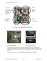
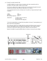
4.2.3 cooking zone power board HOC2000
This board consists of a number of relays, a transformer and other components which are
necessary for the power supply of relays and input boards.
It receives the electrical control signals transmitted by the input boards and supplies the relevant
heating element (cooking zones) with power depending on the impulse/s.
The control relays select the various cooking zones, its number may change according to the type
of appliance.
Voltage:
230V
Frequency:
50Hz/60Hz
Max. working temperature:
85° C
Information A:
The power board is marked with
-
the variant number
-
the production date (week/year)
The various plug tags (BRxx) and relays (Rxx) are specified on the board. These specifications can
also be found on the wiring diagram.
Also on the power board there is a safety temperature limiter which stops the power supply and
switches off the appliance when exceeding a board temperature of 130°C. After a successful
cooling down it switches back again and the built-in cooktop can be put into operation.
Between contact BR19 (neutral) and BR22 (phase) it is possible to measure the mains voltage.
Information A
19 neutral
22 phase
Summary of Contents for COOKING
Page 32: ... 32 DGS TDS N 05 09 A B Electrolux 599 521 367 EN 7 2 Example circuit diagram OVC 1000 ...
Page 33: ... 33 DGS TDS N 05 09 A B Electrolux 599 521 367 EN 7 3 Example circuit diagram OVC 2000 ...
Page 34: ... 34 DGS TDS N 05 09 A B Electrolux 599 521 367 EN 7 4 Example circuit diagram SOEC ...
Page 35: ... 35 DGS TDS N 05 09 A B Electrolux 599 521 367 EN 7 5 Example circuit diagram Prisma ...
Page 36: ... 36 DGS TDS N 05 09 A B Electrolux 599 521 367 EN 7 6 Example circuit diagram HOC 2000 ...
Page 37: ... 37 DGS TDS N 05 09 A B Electrolux 599 521 367 EN 7 7 Operative Equipment Overview ...
Page 38: ... 38 DGS TDS N 05 09 A B Electrolux 599 521 367 EN Changes Pages 26 Chapter 6 1 changed ...


