- 18 -
DGS-TDS-N 05.09 A. B. © Electrolux
599 521 367
EN
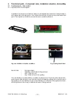
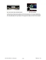
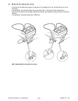
The illustrations show the light bar as a separate component and the electric terminals from the
perspective of the interior of the device, on the left and on the right respectively. The installation
occurs in the truss of the control panel. The control panel must be removed in order to be able to
deinstall the light bar.
4.1.6 Light bar in the control panel
The activation of the light bar occurs through a activation electronics that is hafted on the lower
surface of the front cover. It provides the light bar with a voltage of 7V/18mA.
Summary of Contents for COOKING
Page 32: ... 32 DGS TDS N 05 09 A B Electrolux 599 521 367 EN 7 2 Example circuit diagram OVC 1000 ...
Page 33: ... 33 DGS TDS N 05 09 A B Electrolux 599 521 367 EN 7 3 Example circuit diagram OVC 2000 ...
Page 34: ... 34 DGS TDS N 05 09 A B Electrolux 599 521 367 EN 7 4 Example circuit diagram SOEC ...
Page 35: ... 35 DGS TDS N 05 09 A B Electrolux 599 521 367 EN 7 5 Example circuit diagram Prisma ...
Page 36: ... 36 DGS TDS N 05 09 A B Electrolux 599 521 367 EN 7 6 Example circuit diagram HOC 2000 ...
Page 37: ... 37 DGS TDS N 05 09 A B Electrolux 599 521 367 EN 7 7 Operative Equipment Overview ...
Page 38: ... 38 DGS TDS N 05 09 A B Electrolux 599 521 367 EN Changes Pages 26 Chapter 6 1 changed ...

