- 17 -
DGS-TDS-N 05.09 A. B. © Electrolux
599 521 367
EN
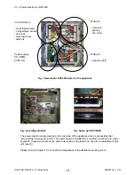
Fig.: Door locking system as complete component
Drive motor
Curve pane
Double micro switch
Above:
Lock
Below:
Oven lighting switch
Sliding micro switch - Lighting
Sliding door locking system
4.1.4.2
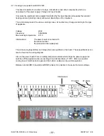
Door locking system, motorics with door-switch light
Switch axis
Electrical terminals
4.1.5 Door switch for the light
When opening the door of the oven, the lighting of the oven is activated over this component after
the device has been switched on. The mounting position is at the top and right-hand corner of the
front frame of the oven
Summary of Contents for COOKING
Page 32: ... 32 DGS TDS N 05 09 A B Electrolux 599 521 367 EN 7 2 Example circuit diagram OVC 1000 ...
Page 33: ... 33 DGS TDS N 05 09 A B Electrolux 599 521 367 EN 7 3 Example circuit diagram OVC 2000 ...
Page 34: ... 34 DGS TDS N 05 09 A B Electrolux 599 521 367 EN 7 4 Example circuit diagram SOEC ...
Page 35: ... 35 DGS TDS N 05 09 A B Electrolux 599 521 367 EN 7 5 Example circuit diagram Prisma ...
Page 36: ... 36 DGS TDS N 05 09 A B Electrolux 599 521 367 EN 7 6 Example circuit diagram HOC 2000 ...
Page 37: ... 37 DGS TDS N 05 09 A B Electrolux 599 521 367 EN 7 7 Operative Equipment Overview ...
Page 38: ... 38 DGS TDS N 05 09 A B Electrolux 599 521 367 EN Changes Pages 26 Chapter 6 1 changed ...

