background image

- 23 -

DGS-TDS-N 05.09 A. B. © Electrolux

599 521 367

EN

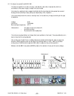
Fig. HOC2000 power board built in the appliance (example built-in cooker)

The assembly position in the appliance is at the right side wall of the housing. For disassembly of
the power board you first have to remove the housing lid. Afterwards you can unscrew both screws
which fix the unit power board and plastic housing from the outside of the appliance.

Note:

A built-in cooker must be removed completely from the built-in cavity for disassembling
the power board.

Summary of Contents for COOKING

Page 1: ...lux Distriparts Muggenhofer Straße 135 D 90429 Nürnberg Germany Fax 49 0 911 323 1022 DGS TDS N Publ Nr 599 521 367 685 05 09 EN Edition COOKING Built in appliances and floor mounted stoves with Avantgarde input electronics ...

Page 2: ...systems 15 4 1 4 1 Door lock 15 4 1 4 2 Door locking system motorics with door switch light 17 4 1 5 Door switch for the light 17 4 1 6 Light bar in the control panel 18 4 2 Functional parts Cooking setting control 19 4 2 1 Power controller 19 4 2 2 Input electronic HOC2000 and Input module 20 4 2 3 cooking zone power board HOC2000 22 5 Technical equipment 24 5 1 Temperature safety device 24 5 2 F...

Page 3: ...interface You also have to be careful with those electronics delivered as spare parts which have to be put out of the ESD protective package only after a potential compensation discharge of possible statical electricity If a potential compensation with an existing static electricity is not executed it does not mean that the electronic is demaged directly Consequential damages may result due to the...

Page 4: ...2 floor mounted cooker Button layout for the M2 flour mounted cooker with double oven Key 1 and 2 Selection button oven function forwards backwards Key 3 Avantgarde menu button Key 4 Confirmation button OK Key 5 MainButton Key 6 Fast heating selection switch Key 7 Selection switch MODE e g clock meat thermometer etc Key 8 and 9 Minus Plus e g for clock meat thermometer etc Key 10 Meat thermometer ...

Page 5: ...ule to set the time of day c If need be confirm with the MODE button Timer button The appliance is ready for operation 2 3 2 Electronic child safe function Basic prerequisites Power supply voltage is connected No oven function selected If the appliance is equipped with a Main Switch then this must be activated To activate and deactivate the child safety function the MODE button Timer button must b...

Page 6: ...tor Grillspieß oven function suggested temperature Boost 1900 1000 1000 1900 40 25 40 25 5 Pos 0 OFF Pos 1 150 B X X X X X X X Pos 2 200 A X X X X X X Pos 3 top bottom el 200 B X X X X X Pos 4 180 C X X X X X X X Pos 5 300 X X X X X X Pos 6 300 X X X X X Pos 7 keeping warm 80 X X X X X Pos 8 30 X X X Pos 9 150 X X X X Pos 10 120 80 X X X X X X X Manual booster A X X X B X X X C X X X X heating ele...

Page 7: ...mp side wall Power W oven function suggested temperature Boost 1900 1000 1000 1900 40 25 40 25 Pos 0 OFF Pos 1 180 X X X X X 2030 Pos 2 top bottom el 200 A X X X X X 2090 Pos 3 190 X X X X X X 3030 Pos 4 200 X X X X X X 3030 Pos 5 250 X X X X X 2990 Pos 6 keeping warm 80 X X X X X 2090 Pos 7 30 X X X X 1105 Pos 8 30 X X X 105 Pos 9 120 80 X X X X X 2030 Booster AUTO A X X X small loads Watt heatin...

Page 8: ...vity temperature of the muffle is approx 500 C A max selection of three pyrolysis durations P can be made per appliance class and equipment Pyrolysis duration Heating period P1 Heatingperiod 150min P2 Heatingperiod 120min P3 Heatingperiod 90min Note In appliances which are equipped with two pyrolysis durations P2 corresponds to the pyrolysis duration P3 3 2 Pyrolitical cleaning Explanation end of ...

Page 9: ...erature of the muffle of approx 130 C it switches off Attention écart pour les appareils stationnaires 3 3 High speed heating Explanation Explanation Quick Heating means reaching the selected oven temperature as quickly as possible After reaching the oven temperature it switches back to the originally selected oven function heating element configuration The Quick Heating function is displayed depe...

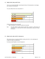
Page 10: ...cutoff of cooking zones If the cooking zones are not switched off after a certain period of time or the temperature not changed they switch off automatically The temporal cutoff depends on the set cooking level Putting into operation after a safety cutoff Switch off appliance or set selection switch to the 0 position Note The safety cutoff is cancelled when the clock function duration or end has b...

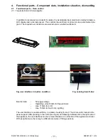
Page 11: ...functions are entered via a so called touchboard Fig user interface in built in condition Fig Locking hook E box Electric data 5V supply voltage Operating current 50mA for the electronic max 110mA for LCD max 150mA for touch incl Lighting The user interface is positioned firmly in a plastic housing E box The whole unit is locked in the panel support After pressing in the notch see figure and drawi...

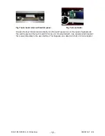
Page 12: ...switch panel Even in the need of replacement the switch panel and the touch board form one unit It is provided with nine sensors which transmit the received impulses to the user interface This happens via a data link in form of a foil conductor Fig Touch board stuck with switch panel Fig Foil conductor ...

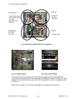
Page 13: ...ents power electronics and plastic box are also a replacement part unit see Ill Please refer to Chapter 7 for connection designations and possible measuring points Fig assembly situation Fig Spare part OVC2000 Fig Powerboard OVC2000 wired in the appliance 4 1 2 Power electronic OVC2000 Connections for meat thermometer Temperature sensor door lock telescopic bars data link Power supply 50 60Hz 230V...

Page 14: ... board The sensor is provided at the rear of the appliance It is used to transmit to the electronic systems the values for cyclic heating the radiators until the selected temperature is reached switch off the radiators in case of overheating of defective sensor switching ON OFF the cooling fan Fig Temperature sensor Fig Electrical resistance of sensor depending on the ambient temperature ...

Page 15: ...hich move a bar into position which then either blocks or releases the lock lever at the baking oven door The system functions during the pyrolysis process independent of the electrical voltage The door lock is switched on at a temperature of the muffle centre of gravity temperature in centre of baking oven of 312 C Unlocking is at a temperature of approx 180 C via a Klixon f11 in wiring diagram T...

Page 16: ... 10 seconds and blocks the lock lever mechanically The door cannot be opened At the same time the internal contact B opens and disconnects the lock path The switch contacts 33 34 close and signal that door lock is completed The electronic signal completes the lock signal Internal contact C closes For unlocking a voltage of 230 V must be applied to contacts 2 and 3 The bar A moves backwards and rel...

Page 17: ...ro switch Lighting Sliding door locking system 4 1 4 2 Door locking system motorics with door switch light Switch axis Electrical terminals 4 1 5 Door switch for the light When opening the door of the oven the lighting of the oven is activated over this component after the device has been switched on The mounting position is at the top and right hand corner of the front frame of the oven ...

Page 18: ...the left and on the right respectively The installation occurs in the truss of the control panel The control panel must be removed in order to be able to deinstall the light bar 4 1 6 Light bar in the control panel The activation of the light bar occurs through a activation electronics that is hafted on the lower surface of the front cover It provides the light bar with a voltage of 7V 18mA ...

Page 19: ... via the bimetallic contact P 1 2 The input voltage of 230 V is applied here Depending on the position of the knob this contact determines how often the hot plate is switched on or off during a certain unit of time by cycling the maximum heating power 230 V or 0 V between contact 2 and 4 refer to performance characteristic Continuous operation at max heating power is hot plate 9 The power characte...

Page 20: ...OC2000 and Input module LED display 3d view description of connection Attention The HOC2000 input electronics also consist of ESD sensitive components Fig input electronic HOC2000 and Input module in installed condition Input electronic HOC2000 Dual circuit heating element Dual circuit regulator ...

Page 21: ...make contact 1 1a of the cooking zone switch input module The make contact is already closed from the first switching step This corresponds to a rotation of 30 see wiring diagram Any other switching step approx 18 results in a change of a resistance value which is transmitted by the conductor plate via data link to the HOC2000 user interface So the input module works like a potentiometer Behind ev...

Page 22: ...he type of appliance Voltage 230V Frequency 50Hz 60Hz Max working temperature 85 C InformationA The power board is marked with the variant number the production date week year The various plug tags BRxx and relays Rxx are specified on the board These specifications can also be found on the wiring diagram Also on the power board there is a safety temperature limiter which stops the power supply and...

Page 23: ...iance is at the right side wall of the housing For disassembly of the power board you first have to remove the housing lid Afterwards you can unscrew both screws which fix the unit power board and plastic housing from the outside of the appliance Note A built in cooker must be removed completely from the built in cavity for disassembling the power board ...

Page 24: ...e fuse Notes for wiring diagram see chapter 7 Deviations possible with floor mounted stoves 5 2 Fan after running The cooling fan switches on automatically when putting the appliance into operation First it is in operation to keep cool the appliance surfaces After the oven was switched off the fan continues running to cool the appliance and then switches off automatically at a centre of gravity te...

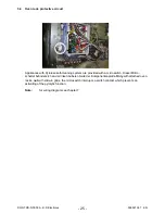
Page 25: ...ing system are provided with a microswitch Dieser Mikro schalter befindet sich an der linken äußeren Seite der Komponentenplatte Only with attached oven racks not with slide in grids the microswitch interrupts a switch contact which prevents an activating of the pyrolytic function Note for wiring diagram see chapter 7 ...

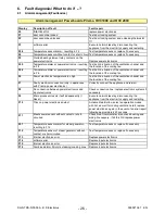
Page 26: ...e cooling fan F7 Faulty electrical connection only in appliances with Prisma power electronics Correctly connect the appliance and re start F8 No connection between power electronics and input electronics Check connection line replace electronic systems if necessary F9 Micro processor resets itself independently Reset Execute network reset by disconnecting the appliance from the electricity supply...

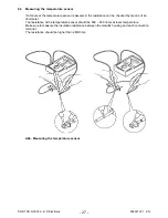
Page 27: ...ssumed the resistance can be checked by means of an ohmmeter The resistance of the temperature sensor should be 500 600 ohms at room temperature Make sure to measure the insulation resistance between the metallic housing and each connection terminal The resistance should be higher than 2 MOhms Abb Measuring the temperature sensor ...

Page 28: ...DS N 05 09 A B Electrolux 599 521 367 EN OBER UNTERHITZE OBER UNTERHITZE Sprache einstellen Language Menu 6 3 Demo Mode input electronic Avantgarde 6 3 1 Activating deactivating Version a Fig 3 Fig 4 Fig 1 Fig 2 ...

Page 29: ... Standby fig 2 Time fig 3 Background illumination for 10 seconds after releasing the main switch Acoustic signal 1x Beep as confirmation Operating step 2 Simultaneous pressing of the two buttons Timer and Minus for 2 seconds fig 4 Acoustic signal 3 x Beep as confirmation Operating step 3 Switching the appliance on with the main switch Display active Demo Mode Time fig 5 even if the appliance is sw...

Page 30: ... a signal sounds The display indicates TEST The factory test ends automatically after 5 minutes By actuating key 7 it can be stopped early 6 4 Factory test Türverriegelungstest The factory test can only be activated if the appliance was disconnected from the supply mains a short time before as a flashing of time is provided ...

Page 31: ... 31 DGS TDS N 05 09 A B Electrolux 599 521 367 EN 7 Wiring diagram measuring points 7 1 Connection Point Overview ...

Page 32: ... 32 DGS TDS N 05 09 A B Electrolux 599 521 367 EN 7 2 Example circuit diagram OVC 1000 ...

Page 33: ... 33 DGS TDS N 05 09 A B Electrolux 599 521 367 EN 7 3 Example circuit diagram OVC 2000 ...

Page 34: ... 34 DGS TDS N 05 09 A B Electrolux 599 521 367 EN 7 4 Example circuit diagram SOEC ...

Page 35: ... 35 DGS TDS N 05 09 A B Electrolux 599 521 367 EN 7 5 Example circuit diagram Prisma ...

Page 36: ... 36 DGS TDS N 05 09 A B Electrolux 599 521 367 EN 7 6 Example circuit diagram HOC 2000 ...

Page 37: ... 37 DGS TDS N 05 09 A B Electrolux 599 521 367 EN 7 7 Operative Equipment Overview ...

Page 38: ... 38 DGS TDS N 05 09 A B Electrolux 599 521 367 EN Changes Pages 26 Chapter 6 1 changed ...

Reviews: