


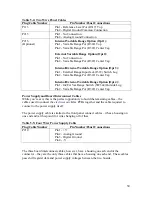


Table 5-4: Two Wire Panel Cables
Plug/Cable Number
Pin Number/Panel Connections
P113
Pin1 - Reference Level Pot (R317) Top
Pin2 - Digital Ground Common Connection
P215
Pin1 - No Connection
Pin2 - Analog Ground Connection
P216
(Optional)
Internal Variable Range Option (Opt 1):
Pin1 - Variable Range Pot (R322) Top
Pin2 - Variable Range Pot (R322) Center Tap
External Variable Range Option (Opt 2):
Pin1 - No Connection
Pin2 - Variable Range Pot (R322) Center Tap
Internal/External Variable Range Option (Opt 3):
Pin1 - External Range Input Jack (J318) Switch Lug
Pin2 - Variable Range Pot (R322) Center Tap
Internal/External Variable Range Option (Opt 4):
Pin1 - Int/Ext Var Range Switch (SW344) Outside Lug
Pin2 - Variable Range Pot (R322) Center Tap
Power Supply and Board Interconnect Cables
While you’re at it, this is the perfect opportunity to build the remaining cables – the
cables used to connect the
electro-music
Klee PCBs together and the cable required to
connect to the power supply itself.
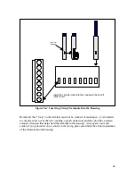
The power supply cable is similar to the front panel connect cables – it has a housing on
one end and (at this point) for wires hanging off of that.
Table 5-5: Four Wire Power Supply Cable
Plug/Cable Number
Pin Number/Panel Connections
P210
Pin1 - +V
Pin2 - Analog Ground
Pin3 - Digital Ground
Pin4 - -V
The three board interconnect cables, however, have a housing on each end of the
connector – they are the only three cables that have a housing on each end. These cables
pass shift register data and power supply voltages between the two boards.
50