


Though the orientation of the remaining switches, aside from the rotary Range Switch,
does not matter at this stage, it’s best to be sure you have the
right
switches in hand when
you’re ready to mount the components.
The gate bus switches are SPDT ON-OFF-ON type switches. The “ON-OFF-ON” label
signifies they have three positions. So, right off the bat, if your switch lever does not
move through three positions, then You Have The Wrong Switch.
On the back of these switches are three terminals. The center terminal will be connected
to either the upper terminal or the lower terminal if the switch level is either full up or full
down. If the lever is in the center position, the center terminal is not connected to either
of the outside terminals.
Go ahead and test your switches – why not now? Make sure they work before you figure
it out when it can be a
real
pain. Take your handy DMM/Ohmmeter/Continuity tester
and attach one lead to the center terminal on the back of the switch. Hold the switch in
the position you plan to mount it on the panel, and flip the lever to the “up” position
(make sure it’s not in the center position). Connect the other lead of your DMM to the
“bottom” terminal on the rear of the switch (opposite of the “Up” direction you just
flipped the switch). You should now have a short between the “bottom” terminal of the
switch and the center terminal of the switch. So, here “up is down” – with the lever of
the switch pointed up, the lower terminal is connected to the center pin. This is an
important fact to tuck away when it comes time to wire things up.
0.00
-----
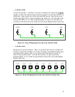
Figure 3-1: SPDT ON-OFF-ON in the “Up” Position
Now, move the switch lever to the center position. The same “lower” terminal you’re
connected to and the center terminal should now read “open”. If not, either the switch is
bad, or you have the wrong type of switch. Now flip the lever of the switch to the
“down” position – you should still read open on the same set of terminals. If not, again
bad switch or wrong type of switch.
11