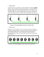


J18
Ext. Range
Signal
Input
Ground
Lug
Tip
Lug
Back
of
Pot
R22
Variable Range
Control
SW44
Ext/Int. Range
Select
SPDT ON-ON
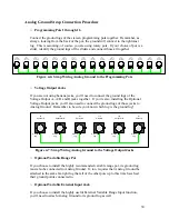
Up Position of Switch Selects External
Range Signal
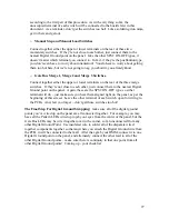
J18
Ext. Range
Signal
Input
Ground
Lug
Tip
Lug
Back
of
Pot
R22
Variable Range
Control
SW44
Ext/Int. Range
Select
SPDT ON-ON
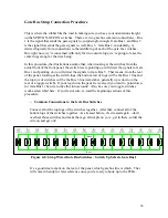
Down Position of Switch Selects External
Range Signal
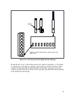
Figure 4-16: Connection of External Range Input Option 4
After all of the strap wiring is done, take the opportunity to test, once again, all of the
switches – make sure they still switch OK after the soldering. If any switch decides it
doesn’t like hot solder applied to its lugs, this is a good time to find out – it’s still
comparatively easy to change it out at this point.
This wraps up all of the notes about putting in the strap connections to the front panel.
Once these connections are made, a good deal of the panel work is already done. Now,
the only thing left to do with the front panel is to install the wires that will connect it to
the PCBs themselves. This is a good time to finish up that portion of wiring, wouldn’t
you think? This is true especially if you’ve decided to use the connectors which will just
plug into your Digital and Analogue Boards. Even if you choose to hardwire it, this is
still a good time to connect the wires.
The next section will deal with building the individual cables that will connect your front
panel components to your boards, then, after that, soldering those cables and wires to
your front panel components.
39