


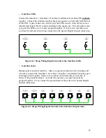


“tip” lug only when a plug is
not
plugged into the jack. You know which lug is your
“tip” lug, so connect one lead of your DMM to that, and connect the other lead to the
“third” lug. If your cable is not plugged into the jack, you should read zero ohms (have
continuity) between these two lugs.
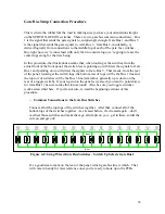
Ground
Lug
Tip
Lug
0.00
n.c.
Switch
Lug
Figure 3-9: No Cable Attached – N.C. Lug Closed
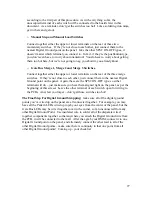
Now plug your cable into the jack. You should now read “open” between these two lugs.
If that’s the case, congratulations, you’ve just located the “n.c. switch” lug. If not, and
there are other lugs, check those. If you don’t find such a lug, then your jack will not
work with that option.
Ground
Lug
Tip
Lug
-------
n.c.
Switch
Lug
Figure 3-10: Cable Inserted – N.C. Lug Open
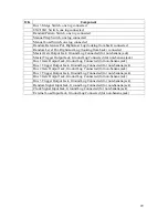
Now comes the time to mount the components! Keep a few things in mind – you
probably want to mount the hardy components first – the jacks, switches and pots. Then
you’ll probably want to attach and align your knobs and (if you’re really into this kind of
stuff) those cool little colored sleeves that fit over toggle switch levers. After that, you’ll
want to go back and put in your LEDs, using the mounting of your choice (which usually
involves an LED holder, or, in the case of those who’ve developed a well established
chrome fetish, chrome LED holders). Use the following tables to ensure that the right
components are mounted in the right places.
17