03/2011 - Art. Nr. 4200 1016 4000C
20
Assembly
Burner assembly
Burner installation position
Checks before commissioning
Burner assembly
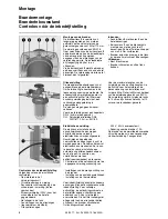
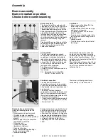
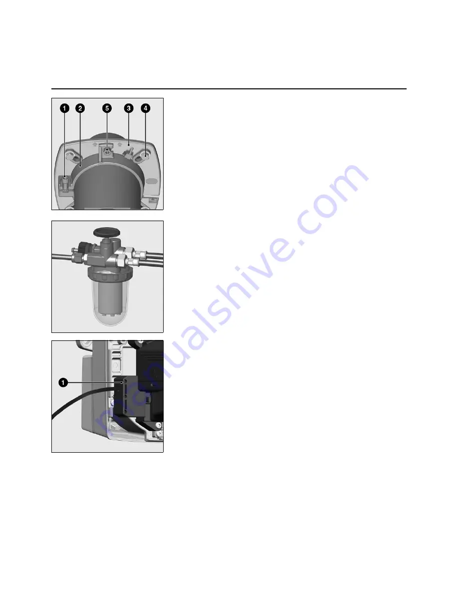
The burner flange
3
is equipped with
elongated holes and can be used with a
hole circle diameter of 150 - 170 mm.
These dimensions comply with EN 226.
Sliding the pipe bracket
2
on the burner
pipe makes it possible to adjust the
installed depth of the combustion head
to the geometry of the combustion
chamber concerned. The installed depth
remains the same during fitting and
removal.
Pipe bracket
2
secures the burner to the
connecting flange and therefore to the
boiler. This completely seals off the
combustion chamber.
Installation:
• Secure connecting flange
3
to the
boiler using screws
4
• Fit pipe bracket
2
to the burner pipe
and secure using screw
1
. Tighten screw
1
to a maximum
torque of 6 Nm.
• Turn the burner slightly, guide it into
the flange and secure using screw
5
.
Removal:
• Loosen screw
5
• Turn the burner out and pull it out of
the flange.
Oil connection
The oil hoses supplied are already
connected to the oil burner pump. The
supply hose is individually marked to
reduce the risk of swapping the hoses.
The oil connection is made by means of
a bleed filter. The filter must be located
in such a way that the correct hose
routing cannot be impaired.
The hoses must not kink.
Cu pipe DN 4 (4x6) should be used as a
fuel-oil tube.
CH: Polyamide fuel-oil tube DN4,
DIN 16773, item no. 501183.
For threshold values for suction line
lengths and suction heights, see the
guideline for planning and dimensioning
plants with suction installations. This
guideline is an integral part of the ELCO
planning criteria.
The suction conduit is passed up to 5 cm
above the tank floor in cubic tanks, and
up to 10 cm above the tank floor in
cylindrical tanks.
Electrical connection
The electrical installation and
connection work must only be carried
out by an authorised electrical specialist.
All applicable rules and regulations must
be observed.
This burner contains electronic
components; it is advisable to connect a
type A FI multipole switch upstream of
the system to detect error currents with
a direct current component.
• Check to ensure that the power supply
voltage is as specified (230 V, 50 Hz)
• Burner fuse: 10 A
The burner and heat generator are
connected by a 7-pin connector
1
.
Checks before commissioning
Check the following points on the
system:
- Water pressure in heating circuit
- Circulation pumps in operation
- Additional air device in flue operable (if
present)
- Power supply (230 V) to the boiler
control panel is ensured
- Oil level in tank
- Oil hose connections
- (feed/return, tightness)
- Open fuel-oil valves
- Burner combustion head settings
- Ignition electrode settings
- Thermostat settings
Before start-up, draw up oil with a hand
pump. Switch on the burner for start-up.
Open the bleed screw at the oil filter to
allow the oil line to bleed fully. Negative
pressure should not drop below 0.4 bar.
Switch off the burner once the oil comes
out free of bubbles and the filter is
completely full of oil. Close the bleed
screw.

