03/2011 - Art. Nr. 4200 1016 4000C
23
Service
Maintenance
Burner and boiler servicing must only
be carried out by a professionally
qualified heating engineer. The
system operator is advised to take
out a service contract to guarantee
regular servicing.
Please observe the following points:
• Disconnect the electrical supply before
carrying out any maintenance or
cleaning work.
Checking the exhaust gas
temperature
• Check the flue gas temperature at
regular intervals.
• Clean the boiler if the flue gas
temperature is more than 30°C above
the value measured at the time of
commissioning.
• To simplify the check, use a flue gas
temperature indicator.
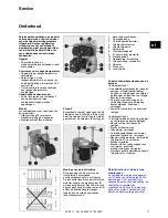
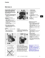
Burner maintenance positions
• After removing the screws
1
, the
equipment plate can be hung in two
maintenance positions.
Position 1
For example, for replacing the nozzle
rod:
• Loosen oil connection
12
• Disconnect connector
9
• Remove electrode block
10
1
Fastening screws
2
Mounting opening
3
Ignition transformed
5
Oil combustion system
6
Oil burner pump
7
Nozzle rod
8
Flame monitor
9
El. connection for nozzle rod
10 Electrode block
11 Regulating screw for combustion
head
12 Oil connection, nozzle rod
13 Nozzle
14 Baffle plate
15 Blower wheel
Maintenance on the burner
Maintenance position 1
• Check oil supply components (tubes,
pumps, oil feed tube) and their con-
nections for leaks or signs of wear,
replace if necessary.
• Check electrical connections and con-
nection cables for damage, replace if
necessary.
• Check pump filter and clean if neces-
sary.
Maintenance position 2
• Clean blower wheel and housing and
check for damage.
• Check and clean the combustion
head.
• Remove baffle plate.
• Replace oil nozzle.
• Check ignition electrodes, readjust or
replace as necessary.
• Fit combustion head. Observe adjust-
ment dimensions (see page 21).
• Fit burner.
• Start burner, check flue gas data,
correct burner settings if necessary.
• Perform flame monitor function check
(see page 22).
Position 2
For instance, for replacing the nozzle
and blower wheel . This position avoids
having to empty the nozzle rod when the
nozzle is changed.
Blower wheel assembly
Observe the positioning diagram below
when replacing the motor and blower
wheel. The inside flange
A
of the blower
wheel must be fitted at the same level as
the equipment plate
B
. Insert a straight
edge between the wing of the blower
wheel and set
A
and
B
to the same
height, tighten the set screw on the
blower wheel (maintenance position 2).
en
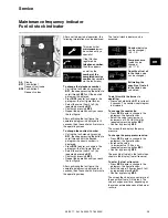
Réinitialisation de l’indicateur de
maintenance
Le symbole de maintenance apparaît
sur l’afficheur du coffret après 30 000
démarrages. C’est pourquoi il est
nécessaire, après chaque entretien, de
réinitialiser le compteur de
maintenance. Pour ce faire, appuyer
pendant au moins 9 secondes sur le
bouton de déverrouillage du coffret.

