


User Manual of Network Video Recorder
136
9.2.6
Configuring Multicast
Purpose:
The multicast can be configured to realize live view for more than 128 connections through network for the device.
A multicast address spans the Class-D IP range of 224.0.0.0 to239.255.255.255. It is recommended to use the IP
address ranging from 239.252.0.0 to 239.255.255.255.
Steps:
1.
Enter the Network Settings interface.
Menu >Configuration> Network
2.
Select the
More Settings
tab to enter the More Settings interface, as shown in Figure 9. 15.
3.
Set
Multicast IP
, as shown in Figure 9. 16. When adding a device to the Network Video Surveillance
Software, the multicast address must be the same as the NVR’s multicast IP.
Figure 9. 16
Configure Multicast
4.
Click the
Apply
button to save and exit the interface.
The multicast function should be supported by the network switch to which the NVR is connected.
9.2.7
Configuring RTSP
Purpose:
The RTSP (Real Time Streaming Protocol) is a network control protocol designed for use in communication
systems to control streaming media servers.
Steps:
1.
Enter the Network Settings menu
Menu >Configuration> Network
2.
Select the
More Settings
tab to enter the More Settings menu, as shown in Figure 9. 15.
Figure 9. 17
RTSP Settings Interface
3.
Enter the RTSP port in the text field of
RTSP Service Port
. The default RTSP port is 554, and you can
change it according to different requirements.
4.
Click the
Apply
button to save and exit the menu.
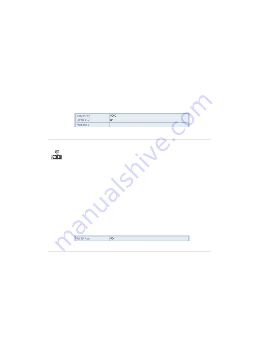
9.2.8
Configuring Server and HTTP Ports
Purpose:
You can change the server and HTTP ports in the Network Settings menu. The default server port is 8000 and the
Summary of Contents for EI-6120 NIP-16
Page 1: ...Network Video Recorder User Manual...
Page 28: ...User Manual of Network Video Recorder 27 12 Click OK to complete the startup Setup Wizard...
Page 41: ...User Manual of Network Video Recorder 40 Figure 3 6 Information...
Page 112: ...User Manual of Network Video Recorder 111 Figure 7 40 Synchronizing...
Page 163: ...User Manual of Network Video Recorder 162 Figure 10 23 View HDD Status 2...


