Options
RCX C-Link User’s Guide
17
EDT, Inc. November 2006
All five CMOS 3.3 V signals go to FPGA 3.3 V I/O pins using series 100-ohm resistors. Custom
firmware can configure these pins as input or output.
NOTE
DB-9 pins 1 and 6 are spare.
Lemo to Female DB-9 RS-232 Cable (Base-mode Cameras Only)
EDT offers an optional Lemo to DB-9 RS-232 cable (part number 016-02445-01), with integrated
CMOS +3.3 V to RS-232 level converters on a small circuit board inside the DB-9 connector shell. This
cable is designed to plug in directly to a host computer serial port.
It offers an auxilliary UART connection over the fiber, in addition to the UART normally associated with
the Camera Link standard. This auxilliary UART can be used, for example, to control the camera’s pan
and zoom servo motors from the host at 19.2 KBaud or less. Alternatively, they can be used for other
low bandwidth signals.
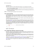
Unlike the
Lemo to Male DB-9 Cable (Base-mode Cameras Only)
discussed above, the DB-9
connector does not supply power to the RCX C-Link. Instead, a red wire (power) and a black wire
(ground), both 24 inches long, are left loose for you to hook up your own power source. The required
power is +4.75 to 18 V DC.
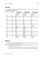
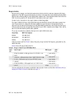
Table 7
shows the color coding for the Lemo to DB-9 RS-232 cable, and how the standard firmware
(in
rgb11.rcx
) uses each wire. DB-9 pins 1, 4, and 6 are wired together and unconnected; 7 and 8
are also wired together, and 9 is also unconnected — these signals are not otherwise used.
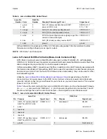
Table 6. Lemo to Male DB-9 Cable Pinout
Lemo Pin
Number Color
DB-9 Pin
Number
Standard Firmware (rgb11.rcx)
Signal Level
1 green
2
AUX_TX, primary auxiliary transmit UART
CMOS +3.3 V
2 red
9
power to RCX C-Link
4.75 – 18 V
3 orange
7
AUX2_TX, secondary auxiliary transmit
CMOS +3.3 V
4 brown
8
AUX2_RX, secondary auxiliary receive
CMOS +3.3 V
5 white
4
SYNC, can be configured as an outgoing copy of the
camera’s Frame-valid signal
CMOS +3.3 V
6 blue
3
AUX_RX, primary auxiliary receive UART
CMOS +3.3 V
7 black
5
ground
ground
Table 7. Lemo to Female DB-9 RS-232 Cable Pinout
Lemo End
DB-9 End
Pin
Purpose
Signal Level
Pin
Purpose
Signal Level
1
UART_TX, auxiliary transmit
UART from
RCX C-Link
CMOS +3.3 V
2
data transmit
RS-232
2
power
red wire out
3
reserved
4
reserved
5
reserved
6
UART_RX, auxiliary receive
UART from
RCX C-Link
CMOS +3.3 V
3
data receive
RS-232
7
ground
5
black wire out

