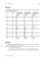
RCX C-Link User’s Guide
Options
EDT, Inc. November 2006
16
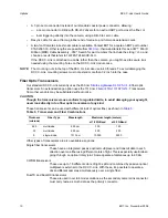
Transceiver Care
Dust in the connectors can cause problems with transceivers. If you suspect such a problem:
1. Direct a blast of compressed air away from any electronic components to blow out any water that
may have condensed in the air nozzle.
2. Blow a blast of compressed air directly into the transceiver ports to dislodge any dust particles that
may have collected in them.
NOTE
It is critical to keep the transceivers clean and dust-free.
Lemo Connector Option
Our standard power connector is a coaxial Switchcraft that locks into place through a threaded sleeve.
We can substitute a 7-pin Lemo connector, EDT part number 016-02445-01, as an option to make the
RCX C-Link more versatile. With the Lemo connector, you can use either of two cables that allow
auxiliary signals.
(On medium- and full-mode extension cord systems, the RCX C-Links at the frame-grabber ends use
the Lemo connectors for the resync cable.)
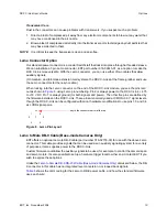
When looking into the Lemo connector on the end of the RCX C-Link module, you see the pins laid
out as shown in
Figure 8
, using Lemo pin numbering. Pin 2 is always power to the RCX C-Link, +4.75
to +18 V DC. Pin 7 is always ground (for both signals and power). The other five pins are defined by
the firmware installed on the RCX C-Link. These pins are normally used at CMOS +3.3 V signal levels,
though the RCX C-Link can be configured with minor hardware modifications to use pins 1,6 and 3,4
as LVDS signal pairs.
Figure 8. Lemo Pin Layout
Lemo to Male DB-9 Cable (Base-mode Cameras Only)
EDT offers an optional Lemo to DB-9 cable (part number 016-02718-00) for use with the above Lemo
connector. This cable provides signals that can be used as an auxiliary signaling system for a variety
of purposes; it also supplies power to the RCX C-Link.
Custom firmware could allow the auxiliary signals to be used, for example, to control the camera’s pan
and servo motors. It’s also possible to set up a hardware trigger local to either end. Contact EDT if you
wish to explore these options.
Unlike the
Lemo to Female DB-9 RS-232 Cable (Base-mode Cameras Only)
discussed below, the DB-
9 connector in this cable has no integrated level conversion, nor looped back signals.
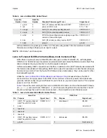
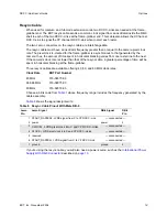
Table 6
shows the color coding for the Lemo to DB-9 power cable, and how the standard firmware
uses each wire:
==
1 6
2 7 5
3 4
key in the connector barrel at the top

