Using the RCX C-Link in Medium and Full Modes
RCX C-Link User’s Guide
7
EDT, Inc. November 2006
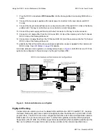
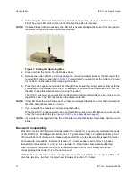
7. Plug the RCX C-Link labeled
YZ Channel FG
into the frame-grabber’s secondary MDR-26 con-
nector.
8. Connect the two power supplies with coaxial power connectors to the two camera-end RCX
C-Links.
9. Connect the resync cable with two Lemo connectors to each of the two RCX C-Links at the frame-
grabber end. The resync cable’s two Lemo connctors are interchangeable.
10. Connect the power supply with the 9-pin D-shell connector to the resync cable connector.
11. Connect an LC duplex fiber from the X channel RCX C-Link at the camera end to the X channel
RCX C-Link at the frame-grabber end.
12. Connect an LC duplex fiber from the YZ channel RCX C-Link at the camera end to the YZ channel
RCX C-Link at the frame-grabber end.
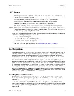
13. g3g3Verify that all four LEDs show a solid green light when power is applied to the camera and
RCX C-Links. See
LED Status on page 8
for details.
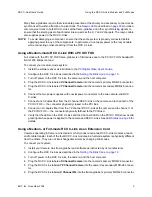
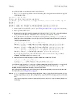
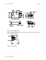
Full-mode extension cords systems are configured as shown in
Figure 6
. Both 850 nm and 1310 nm
systems are configured in the same way; only the part numbers differ.
Figure 6. Full-mode Extension-cord System
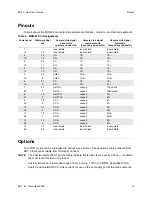
Eighty-bit Packing
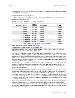
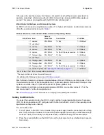
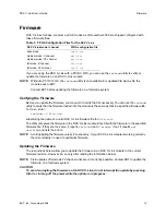
Certain full mode cameras, such as the Basler A04k and Mikrotron MC1310 and MC1311, reassign
the Spare, Data-valid, and Frame-valid control signals to allow the transport of up to 80 bits of data
per pixel clock. The RCX C-Link can be configured with a blink code to accommodate these cameras.
Blink codes of 1-5 (at the camera end) and 2-5 (at the frame-grabber end) allow 80-bit packing at
frequencies of 60–72 MHz. The 72 MHz upper limit is determined by the bandwidth available over the
fiber, but is sufficient to support all modes currently available on the cameras specified above.


