2-14
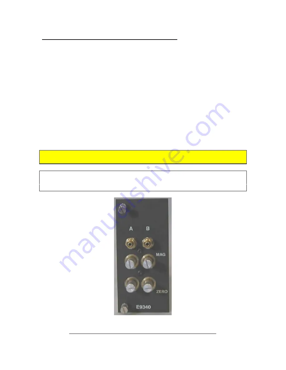
2.10 E9340 (2) Channel A/E Signal Conditioning Module
The E9340 module is a two channel air/electric amplifier which processes pneumatic
information from the air tooling and delivers a conditioned signal to the controller board
of the Accusetter II. The module is mounted in the lower bay of the Accusetter II
The A/E module also contains a ZERO adjustment knob and a MAG adjustment knob for
each input for initial input setup to accommodate the air tooling used..
The air tooling is connected to the air fitting on the front panel of the module. The
recommended length of air line from the module to the air tool is no more than six feet.
A minimum of 60 psi air must be supplied to the filter/regulator assembly on the rear of
the unit. The regulator is factory set to 44 psi.
A jumper strip labeled "A OUT" and "B OUT" provides the option to select a pin, 1 -6,
to output a high level (+/-1.84VDC) signal(s) to the I/O connectors.
Power to the column must be turned off prior to installing or removing a signal
conditioning module.
Refer to the Advanced Operation,
A/E Module Setup
section for additional
information on jumper settings and see Basic Operation,
Setting A/E Mag & Zero
for additional information on setting Mag and Zero for a particular application.
Figure 2.10 - E9340 (2) Channel AE Signal Conditioning Module
Summary of Contents for Accu-Setter II
Page 2: ...A Accu Setter II User s Manual Edmunds GAGES...
Page 16: ...2 3 2 3 Overall E9300Unit Figure 2 1 Accusetter II Basic Unit E9300...
Page 18: ...2 5 Figure 2 2 Front Panel...
Page 20: ...2 7 Figure 2 3 Rear Panel...
Page 32: ...3 4 Figure 3 3 Air Connections For Air Gaging Application Only...
Page 39: ...3 11 An example of various multipliers as related to diameter measurement follows...
Page 40: ...3 12 The last consideration to complete the formula is the gaging function See examples below...
Page 43: ...PROGRAMMING SINGLE CHECK MEASUREMENT 3 15...
Page 44: ...PROGRAMMING SINGLE CHECK MEASUREMENT 3 16...
Page 50: ...PROGRAMMING MULTIPLE CHECK MEASUREMENT 3 22...
Page 51: ...PROGRAMMING MULTIPLE CHECK MEASUREMENT 3 23...
Page 59: ...PROGRAMMING MULTIPLE FIXTURE MEASUREMENT 3 31...
Page 60: ...PROGRAMMING MULTIPLE FIXTURE MEASUREMENT 3 32...
Page 90: ...4 5 Figure 4 3 A E Block...


