9
Before Using the PR-80
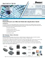
Rear Panel
fig.rearpanel.eps
a. AC Socket
Connect the included power cord here. The selector
switch on the right of this connector must be switched
to match the power supply voltage in the region where
the PR-80 is being used.
b. LAN Connector
Connect a networking cable here. For more detailed
information, refer to “Making the Network Settings”
(p. 113).
c. OUTPUT Jacks [OUTPUT:S-VIDEO,
VIDEO, BNC (COMPOSITE), and
AUDIO]
These are the video and audio output jacks. You use
them to connect such equipment as a television for
monitor use, video projector, power amp, and the like.
d. Input Connectors [INPUT: S-VIDEO,
VIDEO, AUDIO]
Connectors for input of video and audio signals. Use
for connecting video devices and other such
equipment.
e. Mouse Connector [MOUSE]
Use for connecting the included mouse. Make sure the
power to the PR-80 is turned off before connecting.
f. Keyboard Connector [KEYBOARD]
Use for connecting the keyboard. Make sure the power
to the PR-80 is turned off before connecting.
g. USB Connector
Connect an optional remote controller (DV-7DLC),
MIDI interface (SMPU-64/UM-1/UM-1S/UM-1X/
UM-1SX/UM-2/UM-2E/UM-2C/UM-4/UM-550/
UM-880), or a MIDI keyboard (PCR-30/PCR-50/PCR-
80/PC-300) here.
Connect devices here only when the PR-80’s power is
turned off. You can connect to either of the two
connectors. However, you cannot connect two remote
controllers simultaneously.
h. RS-232C Connector [RS-232C]
Use this connector to connect the PR-80 and a
computer and use the connection to exchange signals
between the two devices. For more detailed
information, refer to “Using the RS-232C Connector”
(p. 105).
* You can also use this to connect a touch panel display. In
this case, RS-232C commands cannot be used for control
functions. For more details, refer to “Using a Touch
Panel Display” (p. 105). For more on the touch panel
displays that can be used, contact your dealer.
i. Display Connector [DISPLAY OUT]
Connect the display here. Use an XGA-compatible
display (1024 x 768) equipped with a D-sub 15-pin
connector.
j. DV1 Connector [DV 1]
Digital video input and output connector. Connect
digital video devices here.
* The transition effects and output fader are not applied to
the digital video output.
a
a
b
c
d
g
f
h
i
e
j
PR-80_e.book 9 ページ 2005年1月6日 木曜日 午後9時22分