background image


71 


-


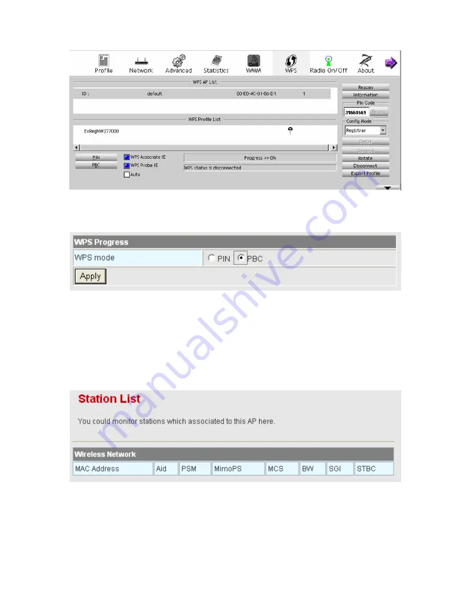
PBC Mode 

Step1 

On the

 Wi-Fi Protected Setup

 page, select the 

PBC

 mode, and then click 

the 

Apply

 button. Or press the 

WPS

 button on the rear panel. 


Step2 

Enable the PBC function on the wireless client. In that case, BR-6224N and 

wireless client will automatically establish connection. 


4.4.5   Station List 

Click 

Wireless 

Station List 

to display the 

Station List

 page. 


On this page, you can view the wireless networks that connect to the BR-6224N. 

Summary of Contents for BR-6224n

Page 1: ...1...

Page 2: ...to time in the contents hereof without obligation to notify any person of such revision or changes The product you have purchased and the setup screen may appear slightly different from those shown i...

Page 3: ...on to PPPoE ADSL and DHCP Auto config 10 3 3 Connection Introduction for Ethernet User 12 3 4 Connection Introduction for Wireless User 12 3 5 Logging In to the Web Page 15 4 Web Configuration 17 4 1...

Page 4: ...4 5 8 Wps 99 4 5 9 About 101 4 6 Firewall 101 4 6 1 Filtering 101 4 6 2 Virtual Server 105 4 6 3 DMZ 108 4 6 4 System Security 108 4 6 5 Content Filtering 110 4 7 Administration 113 4 7 1 Management...

Page 5: ...Network Connection Modes Describes how to configure the network settings and provides the introduction to network connection modes Chapter 4 Web Configuration Mainly describes how to navigate through...

Page 6: ...WPA2 PSK WPA WPA2 Enterprise and Dynamic WEP 802 1x Support 5 types of WAN connection modes including STATIC fixed IP DHCP Auto config PPPoE ADSL L2TP and PPTP Support remote access control Support fi...

Page 7: ...and OFDM and its data rate is up to 150 Mbps It is easy to install and can be applied to AP and router access BR 6224N provides 64 bit and 128 bit WEP encryption schemes and WPA encryption associating...

Page 8: ...lly Off Power is off or the device is down Green On Radio switch is turned on Green Blink Data is being transmitted Off Radio switch is shut off WPS Green On Connection succeeds under Wi Fi Protected...

Page 9: ...hub switch or computer on LAN WPS This button is used for enabling WPS PBC mode If WPS is enabled press this button and then AP starts to accept the negotiation of PBC mode Note Do not press the Reset...

Page 10: ...evice to the computer hub router or switch the Ethernet cable should be less than 100 meters Do not place this device on an unstable surface or support Do not put this device on the ground Keep the de...

Page 11: ...ng from one AP to another AP correctly In that case the wireless client terminal can communicate with the other devices within the BR 6224Ns coverage In order to realize the wireless client roaming am...

Page 12: ...N is 192 168 1 1 The subnet mask is 255 255 255 0 The DHCP Server is enabled It is recommended you set the network adapter to be Obtain an IP address automatically Your PC automatically acquires IP ad...

Page 13: ...Area Connections Properties appears Note If there are several network cards on your PC it may not display the Local Area Connections Properties page It may display other dialog boxes Step3 Double cli...

Page 14: ...address and enter the IP address of the network adapter The IP address should belong to the IP network segment 192 168 1 X X is a number between 2 and 254 Step5 Set the subnet mask and then click the...

Page 15: ...168 2 1 in the dialog box See the following figure Note 192 168 2 1 is the default IP address of the LAN interface If this IP address is changed and you need to ping the IP address of the BR 6224N yo...

Page 16: ...ISP office end and make sure that the communication between both sides is normal Set your ADSL or cable modem to be bridge mode For more details please refer to ADSL or cable modem user manual or cons...

Page 17: ...Ethernet cable to connect the uplink interface of router or gateway to the WAN interface of the BR 6224N Step2 Use one Ethernet cable connects your PC to the LAN interface of the BR 6224N Set the TCP...

Page 18: ...Usually users using the LAN interfaces of the BR 6224N need to set the network adapter to be Obtain an IP address automatically If any user wants to manually set the TCP IP properties please refer to...

Page 19: ...e refreshed The default SSID of the BR 6224N is Edimax Router Choose the AP that you want to connect and then click the Connect button The default wireless security mode is Disable and you can connect...

Page 20: ...d you need to enter the encryption key in the field of network key and then click the Connect button Step4 If the wireless network card connects to BR 6224N successfully the character Connected will a...

Page 21: ...s please refer to 4 4 Wireless Settings Gateway Mode Note After your wireless network card connects to AP successfully usually you should set the network adapter to be Obtain an IP address automatical...

Page 22: ...16 After clicking the OK button on the login page you can log in to the Web page...

Page 23: ...4 1 Overview After finishing login system displays the Overview page The Overview page includes Status Statistic and Management submenus 4 1 1 Status Click Status on the Overview page to display the a...

Page 24: ...ernet configuration and local network settings 4 1 2 Statistic Click Statistic on the Overview page to display the Statistic page This page displays the memory status the numbers of transmitted and re...

Page 25: ...anagement Click Management on the Overview page to display the System Management page This page provides administration settings NTP settings and DDNS settings For more details please refer to 4 7 1 M...

Page 26: ...lows routing between WAN and LAN or WAN and wireless network WISP In the WISP mode all the Ethernet interfaces can access the Internet by wireless routing NAT Enabled This function can only be used in...

Page 27: ...21 The sub menus of the Internet include LAN WAN Advanced Routing DHCP and QoS 4 3 1 LAN Click Internet Lan to display the Local Area Network LAN Settings page...

Page 28: ...22...

Page 29: ...DHCP service you can configure the following parameters of the DHCP server z Start IP Address The start IP address of the DHCP address pool z End IP Address The end IP address of the DHCP address pool...

Page 30: ...Proxy Enable or disable DNS Proxy After enabling this function the devices on the LAN where AP acts as a proxy can send domain resolution request to AP After finishing the settings click the Apply bu...

Page 31: ...e device that connects to the AP s WAN interface The default setting is Disable STATIC fixed IP On the Wide Area Network WAN Settings page select STATIC fixed IP as the WAN connection type and the fol...

Page 32: ...t mask the gateway and the DNS server address After finishing the settings click the Apply button to apply the settings PPPoE ADSL If you want to use PPPoE service please select PPPoE ADSL connection...

Page 33: ...gs page select L2TP as the WAN connection type and the following page appears On this page enter the server IP the username and the password provided by the ISP Set the IP address the subnet mask and...

Page 34: ...me and the password provided by the ISP Set the IP address the subnet mask and the default gateway When the Address Mode is Dynamic the IP address the subnet mask and the default gateway of the WAN in...

Page 35: ...29 This page is used to manage the routing rules view the routing table and set the routing RIP function Add a Routing Rule...

Page 36: ...Host or Net Gateway The IP address that the routing rule passes Netmask When the range is Net you can set this option Interface The local legal interface that the routing rule passes You may select L...

Page 37: ...e After enabling RIP function AP can refresh its routing information and send RIP information to other devices 4 3 4 DHCP Client Click Internet DHCP to display the DHCP Client List page On this page y...

Page 38: ...e Enable or disable QoS The default QoS setting is Disable After enabling QoS you may set the upload bandwidth of the WAN interface Upload Bandwidth You may self define the bandwidth or select a prope...

Page 39: ...join any group If the new rule joins a group it indicates that the minimum and the maximum available bandwidths of the new rule are the same as the preset values of the group that it joins Modify the...

Page 40: ...is large this value shows that the minimum bandwidth that this group can share Its value range is between 1 and Ceil value Ceil When the data flow is small this value shows that the maximum bandwidth...

Page 41: ...address The destination IP address of the rule If data packets include the IP address the data packets are placed into the group Src IP address The source IP address of the rule If data packets inclu...

Page 42: ...If data packets match the parameters above you can determine whether to remark DSCP The default setting is Auto After finishing the settings click the Add button to add the new rule Delete a QoS Rule...

Page 43: ...37...

Page 44: ...s 30 20 5 and 10 You can also delete the default rules if necessary The examples of QoS Settings Set the Upload Bandwidth On the Quality of Service Settings page enable the QoS and set the upload band...

Page 45: ...of the corresponding group and you can modify the attribute settings of the corresponding group Let s take High group as an example On this page set the Rate value to be 30 If the upload bandwidth is...

Page 46: ...up and select the ICMP protocol After finishing the settings click the Add button to add the new rule About DSCP DSCP consists of 6 bits of IP packet header It uses ToS field This byte is also called...

Page 47: ...crete values as follows Service level priority Type 1 Type 2 Type 3 Type 4 Low discarding priority AF11 10 AF21 18 AF31 26 AF41 34 Medium discarding priority AF12 12 AF22 20 AF32 28 AF42 36 High disca...

Page 48: ...42 On this page you may set the parameters of wireless network WDS and HT...

Page 49: ...cription Radio On Off Enable or disable the wireless switch Network Mode You may select a proper network mode in the drop down list 11b g mixed mode 11b only 11g only 11b g n mixed mode default Networ...

Page 50: ...same AP can not communicate each other MBSSID AP Isolation Enable or disable the isolation among different SSIDs After enabling this function the client terminals with different SSIDs can not communi...

Page 51: ...key Bridge Mode The parameters of Bridge Mode are described as follows Field Description WDS Mode Select the Bridge Mode Phy Mode The physical modes in the drop down list include CCK OFDM HTMIX and GR...

Page 52: ...the Bridge Mode HT Physical Mode The parameters of HT Physical Mode are described as follows Field Description Operation Mode You may select Mixed Mode or Green Field The default operation mode is Mix...

Page 53: ...20 MHz bandwidths together to form a 40MHz bandwidth Actually the 40MHz bandwidth can act as two 20 MHz bandwidths One is the primary bandwidth the other is the secondary bandwidth When data is being...

Page 54: ...order to insure the security of the data transmission 802 11n protocol requires that if the client receives a unicast frame it should immediately send back a ACK frame After the receiver of A MPDU rec...

Page 55: ...49 On this page you may configure advanced wireless parameters such as beacon interval data beacon rate and Tx power...

Page 56: ...ion BG Protection Mode You may select On Off or Auto The default BG protection mode is Auto Beacon Interval By default wireless beacon signal sends data to station every other 100 ms The range is 20 9...

Page 57: ...nd Voice Over IP telephony Short Slot Enable or disable short slot Tx Burst Tx Burst can be used to improve the efficiency of data transmission It can make system transmit more data during a period of...

Page 58: ...figuration page of WMM parameters Multicast to Unicast Converter Enable or disable Multicast to Unicast After enabling this function the transmission quality of wireless multicast stream can be improv...

Page 59: ...or all the devices When each priority queue waits for sending packets it has to wait a fixed time AIFSN and a random time CW They define time values by multiple time slots For 802 11b its time slot is...

Page 60: ...Field Description Aifsn Aifsn Arbitrary Inter Frame Space Number This parameter influences the delay time of WMM access category If you use voice or video service you d better set this parameter to b...

Page 61: ...echo request If you set this value is 0 it means AP does not send back an echo request which will bring positive effect for WMM If this value is 1 AP generates the response to the request DLS Direct L...

Page 62: ...button Step4 If DLS succeeds you can view the MAC address of wireless card A on the WMM page of wireless card B and vice versa 4 4 3 Security Click Wireless Security to display the Wireless Security E...

Page 63: ...uthorized access and monitoring Select SSID SSID choice select the SSID that you want to configure Security Mode This page provides 10 types of security modes including OPEN SHARED WEPAUTO WPA Enterpr...

Page 64: ...s of OPEN mode are described as follows Field Description Security Mode Select OPEN Default Key Select a key as the default key WEP Keys WEP Key 1 2 3 4 Set 64 bit or 128 bit key The key format is Hex...

Page 65: ...rity Mode Select SHARED Encrypt Type You may select WEP or None Default Key Select a key as the default key WEP Keys WEP Key1 2 3 4 Set 64 bit or 128 bit key The key format is Hex or ASCII WEPAUTO The...

Page 66: ...ewal Interval Set the key renewal interval IP Address The IP address of RADIUS server Port The default port number is 1812 You may change it according to the server setting Shared Secret The shared ke...

Page 67: ...WPA PSK mode are described as follows Field Description Security Mode Select WPA PSK WPA Algorithms Select TKIP or AES Pass Phrase Set 8 bit to 64 bit key Key Renewal Interval Set the key renewal inte...

Page 68: ...se Master Key cache period PMK scheme allows the roaming users that pass through the 802 11X EAP handshake protocol roam to the previous AP again PMK can decrease the roaming delay and improve the roa...

Page 69: ...e limit Idle Timeout Set the idle timeout WPA2 PSK The parameters of WPA2 PSK mode are described as follows Field Description Security Mode Select WPA2 PSK WPA Algorithms You may select TKIP AES or TK...

Page 70: ...refer to WPA2 PSK WPA1 WPA2 Enterprise The parameters of WPA1 WPA2 Enterprise are described as follows Field Description Security Mode Select WPA1 WPA2 Enterprise WPA Algorithms You may select TKIP AE...

Page 71: ...imit Idle Timeout Set the idle timeout Dynamic WEP 802 1X The parameters of Dynamic WEP 802 1X mode are described as follows Field Description Security Mode Select Dynamic WEP 802 1X IP Address The IP...

Page 72: ...Allow the access control to the wireless devices in the MAC list Reject Reject the access control to the wireless devices in the MAC list Add a station Mac Enter the MAC address of wireless device th...

Page 73: ...67 On this page you can modify the WPS settings WPS can make your client automatically synchronize with the AP setting and establish connection WPS Config...

Page 74: ...s related to WPS WPS Summary WPS summary displays the preset WPS information such as WPS current status WPS authentication mode and WPS encryption type Click the Reset OOB button on the Wi Fi Protecte...

Page 75: ...S Status The figure above displays WPS current status WPS Application This page provides two WPS modes including PIN and PBC modes At present WPS supports three types of operation modes including Enro...

Page 76: ...i Protected Setup page enter the PIN code of wireless client for example 12345678 Step3 Click the Apply button on the Wi Fi Protected Setup page to submit the setting Registrar Mode Step1 View the AP...

Page 77: ...S button on the rear panel Step2 Enable the PBC function on the wireless client In that case BR 6224N and wireless client will automatically establish connection 4 4 5 Station List Click Wireless Stat...

Page 78: ...e For better compatibility please try to adopt the products with the same model to connect to the BR 6224N WDS Repeater Mode In the Repeater mode you can use the BR 6224N to connect to the primary rou...

Page 79: ...p3 On the Basic Wireless Settings page set the WDS mode to be Repeater Mode set the physical mode and the encryption type of AP to accord with that of peer AP and then enter the MAC address of the pee...

Page 80: ...74 Step4 Click Wireless Security to display the Wireless Security Encryption Settings page...

Page 81: ...ess card does not directly communicate with the wireless device that accesses the Internet but it directly communicates with the BR 6224N Step1 On the Basic Wireless Settings page select the WDS mode...

Page 82: ...es for example WPA PSK WPA2 PSK WDS Lazy Mode In the Lazy mode the BR 6224N automatically connects to the WDS devices that use the same SSID channel encryption mode and physical mode You do not need t...

Page 83: ...Lazy mode Step2 On this page set the security mode of the BR 6224N to accord with the peer AP Note In the WDS mode do not set any mixed modes for example WPA PSK WPA2 PSK Do not set all the WDS APs to...

Page 84: ...ble shows the settings of AP1 and AP2 Set AP1 Step1 Enter http 192 168 1 1 in the IE address bar and then enter the user name by default admin and the password by default admin to log in to the Web pa...

Page 85: ...79 Step3 Set the SSID of AP1 AP1 and AP2 must use the same SSID and channel...

Page 86: ...Internet LAN to display the Local Area Network LAN Settings page Set the IP address of AP1 to be 192 168 1 1 Step6 Click Administration Statistics to display the Statistic page On this page you can vi...

Page 87: ...Settings page set the WDS mode to be Bridge Mode and enter the MAC address of the AP1 4 5 Wireless Settings WISP Mode In the WISP mode the following figure shows the navigation menu of the Wireless s...

Page 88: ...to display the Station Profile page On this page you can add a new profile delete edit and active a preset profile in the profile list Add a Profile Click the Add button on the Station Profile page an...

Page 89: ...stem Configuration page are described as follows Field Description Profile Name Set a profile name SSID Enter the SSID of AP that you want to connect Network Type Infrastructure An application mode fo...

Page 90: ...o be 802 11 Ad hoc you may select a proper channel in the drop down list 11B Preamble Type When selecting the network type to be 802 11 Ad hoc you are allowed to set the 11B preamble type You may sele...

Page 91: ...y When selecting 128 bit 26 hex digits 13 ascii keys it allows you to set 26 hex digit or 13 ASCII character key WEP Key Entry Method You may select Hexadecimal or ASCII text WEP Keys WEP key 1 4 For...

Page 92: ...hrase Set the encryption key Delete a Profile If you want to delete a preset profile e g PR0F001 choose this profile and then click the Delete button See the following figure Edit a Profile If you wan...

Page 93: ...PROF001 such as SSID network type and security mode Activate a Profile If you want to delete a preset profile e g PR0F001 choose this profile and then click the Activate button The activated file will...

Page 94: ...88 4 5 2 Link Status Click Wireless Link Status to display the Station Link Status page...

Page 95: ...89 On this page you can view the connection status of AP in the STA mode 4 5 3 Site Survey Click Wireless Site Survey to display the Station Site Survey page...

Page 96: ...k the Connect button If this AP is not encrypted click the Apply button on the following page to establish connection If this AP is encrypted click the Connect button and the following page appears If...

Page 97: ...le will be refreshed Add a Profile On the Station Site Survey page select an AP in the Site Survey table and then click the Add Profile button to enter System Configuration page On System Configuratio...

Page 98: ...iew the status of transmitted and received data Click the Reset Counters button and then the data statistic information can be refreshed 4 5 5 Advance Click Wireless Advance to display the Station Adv...

Page 99: ...wireless function configure the wireless advanced properties and set the HT physical mode Advance Configuration The parameters of Advance Configuration are described as follows Field Description Wirel...

Page 100: ...ciency will also be reduced You may select Auto On or Off Auto If selecting this option AP enables or disables the B G protection mode according to the network status On Enable the B G protection mode...

Page 101: ...ode or GF Green Field The default setting is MM BW Bandwidth You may select 20 or Auto GI Guard Interval You may select Long or Auto MCS MCS Modulation and Coding Scheme is for denoting the WLAN data...

Page 102: ...96 This page is used to configure the wireless QoS properties in the station mode QoS Configuration The parameters of QoS Configuration are described as follows Field Description...

Page 103: ...LS After enabling direct link setup you are allowed to set the MAC address and the timeout value The parameters of Direct Link Setup are described as follows Field Description MAC Address Enter the MA...

Page 104: ...s PLCP Preamble and PLCP Header that are needed to send an 802 11 message and the system throughput is improved You may select Manual or Auto MPDU density IF selecting Manual you are allowed to set th...

Page 105: ...be an 802 11 message In this way PLCP Preamble PLCP Header and 802 11 MAC overhead that are needed for sending an 802 11 message decrease At the same time the acknowledge frames also decrease and the...

Page 106: ...urvey list will be refreshed Mode It provides Enrollee mode and Registrar mode Enrollee mode if selecting this mode you need to enter Station PIN on AP for WPS connection Registrar mode If selecting t...

Page 107: ...address 4 6 Firewall The following figure shows the navigation menu of Firewall Firewall is an advanced setting which is used to block or allow the data packets that pass through the AP The sub menus...

Page 108: ...102...

Page 109: ...IP Port Filtering Enable or disable MAC IP Port filtering The default setting is Disable Default Policy By default AP will accept all the packets that do not match any rule MAC IP Port Filter Setting...

Page 110: ...IP Port Filter Settings are described as follows Field Description MAC Address The MAC addresses included in the data packets It can be a destination MAC address or a source MAC address Dest IP Addre...

Page 111: ...xpected traffic on the Internet from your host on the LAN The virtual server can create a channel that can pass through the firewall In that case the host on the Internet can communicate with a host o...

Page 112: ...106 Virtual Server Settings...

Page 113: ...ngs IP Address Enter the IP address that you allow to access Protocol Select the protocol that you allow to access You may select TCP UDP or TCP UDP Port Range Enter the port range that you allow to a...

Page 114: ...Firewall DMZ to display the DMZ Settings page The parameters of DMZ settings are described as follows Field Description DMZ Settings Enable or disable the DMZ settings DMZ IP Address Enter the IP addr...

Page 115: ...sable remote management You may select Deny or Allow If selecting Allow users in other regions can access the Internet and configure AP Ping from WAN Filter Enable or disable the filter Note When the...

Page 116: ...ternet If there is a connection open that applies to the packet that has arrived from the Internet this incoming packet is let through otherwise this incoming packet is rejected Compared to the NAT fi...

Page 117: ...111 Webs Content Filter...

Page 118: ...e following table Filter Description Proxy For filtering the proxy pages Java For filtering pages that use Java script ActiveX For filtering plug in pages Current Webs URL Filters The figure above sho...

Page 119: ...d a Host keyword Filter Keyword Enter the key words of the host that needs to be filtered After finishing the settings click the Add button to add a new host filter 4 7 Administration The following fi...

Page 120: ...114 4 7 1 Management Click Administration Management to display the System Management page...

Page 121: ...inistrator Settings are described as follows Field Description Account Enter the account that you want to change Password Enter the password for the new account Note If you forget the account and the...

Page 122: ...onize its time with your PC Time Zone Select your proper time zone NTP Server Enter the URL of the time server NTP synchronization hours Set the interval for synchronizing with the time server DDNS Se...

Page 123: ...the Browse button to choose the correct new firmware and then click the Apply button System begins to upgrade firmware After upgrading firmware system reboots and automatically enters the Web page No...

Page 124: ...your local PC Import Settings Click the Browse button to choose the settings on your PC and then click the Import button to import the settings to AP Load Factory Defaults Click the Load Default butto...

Page 125: ...119 This page displays system information Internet configuration and local network settings 4 7 5 Statistic Click Administration Statistics to display the Statistic page...

Page 126: ...120 This page displays the memory status the numbers of transmitted and received data packets of the WLAN LAN and WAN...

Page 127: ...System Log page On this page you are allowed to set the log server and view the system log After enabling the remote log server and entering the IP address of the server click the Apply button and th...

Page 128: ...and Delete Files respectively Why you can not establish the network connection Beyond the wireless coverage 1 Place the device near to the client 2 Try to change the channel setting Authentication pr...

Page 129: ...Replace a network cable to connect to the device Why you can not access the Internet 1 Check whether the LEDs status on the ADSL modem and the wireless device is normal 2 Check whether the WAN indica...

Page 130: ...124...

Page 131: ...125...

Reviews: