background image

Acclarix LX4 Diagnostic Ultrasound System User Manual                                                    Getting Started 

- 32 - 

3.9 Monitor Position Adjustment 

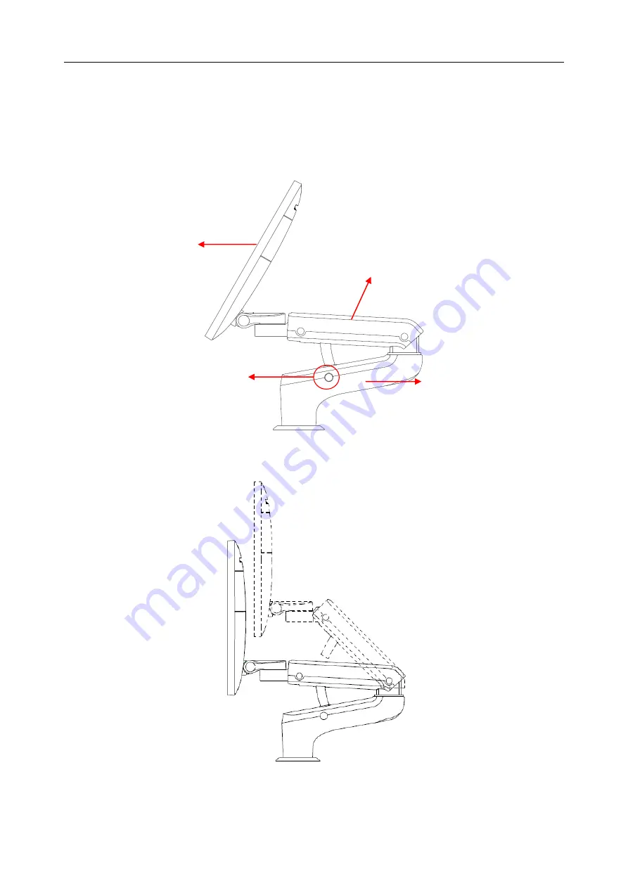
3.9.1. Adjusting the Position of Monitor with Z-shaped Support Arm 

Before adjusting the position of the monitor, you need to unlock the upper support arm. To unlock 

the upper support arm, press the release button(see the figure below).   


Adjusting the height 

Move the upper support arm up or down to adjust the height.   


Release 

Button 

Monitor 

Upper Support Arm 

Lower Support 
Arm 

Summary of Contents for Acclarix LX4

Page 1: ...n 1 0 Product Model Acclarix LX4 Project Code 2911G003 Signature Originator xiejuyan 2019 08 19 14 34 48 Reviewers lijuan 2019 08 19 17 35 41 Reviewers luyingjun 2019 08 20 15 01 34 Reviewers chenyunf...

Page 2: ...1...

Page 3: ...ad and understand all instructions in this manual prior to using the Acclarix LX4 ultrasound system Disregarding instructions particularly warnings and cautions is considered abnormal use Caution Fede...

Page 4: ...II Regulatory Approval Remarks Auto OB measurement IS NOT available in the USA and its territories...

Page 5: ...3 8 Trackball 31 3 9 Monitor Position Adjustment 32 4 Exam Operation 36 4 1 How to Start an Exam 36 4 2 How to End an Exam 36 4 3 How to Restart an Exam 37 4 4 The Patient Information Page 37 4 5 Mod...

Page 6: ...tion 69 6 3 3 Sterilization 72 6 3 4 Storage 72 6 3 5 Using Transducers 73 7 Features 75 7 1 Comments 75 7 2 Body Mark 77 7 3 Measurements 78 7 3 1 Generic Measurements 80 7 3 2 Application Measuremen...

Page 7: ...6 12 Troubleshooting and Maintenance 137 12 1 Daily Checklist 137 12 2 Troubleshooting 137 12 3 Cleaning the System 138 12 3 1 Cleaning the System Surface 139 12 3 2 Cleaning Trackball 139 12 3 3 Need...

Page 8: ...sociated ultrasound transducers The system circuitry generates an electronic voltage pulse which is transmitted to the transducer In the transducer a piezoelectric array converts the electronic pulse...

Page 9: ...fer to User Manual Background Blue Symbol White 8 Caution 9 Biological Risks 10 CE Marking 11 Authorized Representative in the European Community 12 Disposal method Indicates that the equipment should...

Page 10: ...ing 21 Network port 22 Trademark 23 Video Output port 24 USB 2 0 port 25 USB 3 0 port 26 Microphone input 27 Headphones 28 Up Down button to move the control panel up or down 29 Forbid to move the sys...

Page 11: ...erile Indicates a medical that has not been subjected to a sterilization process The following labels are used on the wooden packaging No Symbol Definition 1 This way up 2 Fragile handle with care 3 K...

Page 12: ...t environment or when the relative humidity exceeds 95 Do not touch the connector pins on the transducer port Parts and accessories used must meet the requirements of the applicable IEC EN60601 series...

Page 13: ...setup to provide power to the ultrasound system or to the system s peripheral devices may compromise the system grounding and cause the system to exceed current leakage limits It is not suggested to u...

Page 14: ...e to the equipment cables and transducers If a component is damaged replace it before use Do not use in locations subject to vibration Read and understand the section A1 2 Ultrasound Safety and the AL...

Page 15: ...sonnel The device and accessories are to be disposed of according to local regulations after their useful lives Alternatively they can be returned to the dealer or the manufacturer for recycling or pr...

Page 16: ...pgrade Make sure the ultrasound system is used under secure network environment and all the approved devices connecting with the ultrasound system are physically secure Anti virus measures such as USB...

Page 17: ...iption BGK C5 2 BGK C5 2 Needle Guide Bracket Kit For use with the C5 2D Supports 16G 18G 20G 22G BGK L40UB BGK L40UB Needle Guide Bracket Kit For use with the L12 5D Supports 16G 18G 20G 22G BGK CR10...

Page 18: ...nd click the Add button Once it is added confirm correct operation by clicking the Test button If that does not work you may need to download a printer ppd file from the printer supplier In that case...

Page 19: ...Acclarix LX4 Diagnostic Ultrasound System User Manual Getting Started 12 3 2 System Overview 3 2 1 Front View Figure 3 1 Front View 10 11 14 13 12 7 3 4 2 9 5 1 6 8...

Page 20: ...der 11 Transducer holder 5 Control Panel 12 Up Down button 6 Handle 13 Main unit 7 Keyboard 14 Wheels four Table 3 3 Front View ports Use the Up Down button to move the control panel up or down Press...

Page 21: ...Acclarix LX4 Diagnostic Ultrasound System User Manual Getting Started 14 3 2 2 Rear View Figure 3 3 Rear view of the device with Z shaped monitor arm 3 4 2 1 5...

Page 22: ...C shaped monitor arm 1 Table for placing printer 2 Cable holders two 3 Peripheral cable access panel door 4 Heat dissipation orifice 5 Filter Table 3 4 Rear View ports CAUTION 1 Ensure system vents ar...

Page 23: ...Acclarix LX4 Diagnostic Ultrasound System User Manual Getting Started 16 3 2 3 Left View Figure 3 5 Left view of the device with Z shaped monitor arm 1 2...

Page 24: ...ic Ultrasound System User Manual Getting Started 17 Figure 3 6 Left view of the device with C shaped monitor arm 1 USB 2 0 Ports two 2 DVD drive Table 3 5 Left View ports NOTE USB ports here can only...

Page 25: ...0 interface 4 Equipotential terminal 8 DVI port 12 HDM Port Table 3 6 I O port interface 3 3 Connecting and Disconnecting a Transducer NOTE Ensure that the system is shut down or the image is frozen...

Page 26: ...cking handle counterclockwise to the horizontal position 5 Align the connector with the transducer port and carefully push into place 6 Turn the locking handle on the transducer connector clockwise to...

Page 27: ...in unit 2 Only plug C5 2MD transducer in the leftmost transducer socket socket 1 If user connect transducer C5 2MD to other three transducer sockets a message of Probe C5 2MD cannot be connected to th...

Page 28: ...sword are forgotten please contact the serviceman for the system password reset 2 It is not suggested to use Emergency login under non Emergency situation Please login the system with your account or...

Page 29: ...the Power on off key for about 5s will shut down the system directly NOTE 1 Turn off and unplug the device after use 2 Please unplug the power cable from the power socket prior to storage Sleep mode...

Page 30: ...his field also contains data fields for The currently active transducer The currently active preset MI TI current date and time Image Field The ultrasound image appears in the Image field under the In...

Page 31: ...t with a configured Server Clicking on this icon displays a queue of exam or image transfers and as well as the transfer status of each exam or image including refuse pending active success and fail F...

Page 32: ...is activated clicking on this icon shows a WiFi Turn off button and shows a list of all Wi Fi networks that are currently available Selecting an available network displays a dialog box for entering p...

Page 33: ...off the system 2 Utilities Press this button to get the Set Up Maintenance Connectivity Screen Adjust keys etc on the touch screen 3 F1 User defined button 4 F2 User defined button 5 Patient Invokes t...

Page 34: ...t can rotate the image by the X axis of the activated window 13 PW Press to get the sample line Use the trackball to adjust the position and press this knob again to display the Doppler strip display...

Page 35: ...for details 23 Depth Rotate the knob to adjust the depth of the image displayed Rotate counterclockwise to decrease the depth and rotate clockwise to increase 24 Focus Press this knob to adjust the nu...

Page 36: ...e adjusted separately Glide the slide controls to adjust the TGC Glide the upper segments to adjust the near field gain and the lower segments to adjust the far field gain glide rightward to increase...

Page 37: ...ously change the value Each touch screen page displays at most six paddles Below each paddle there is a knob on the console used to change its setting Pressing and dragging one paddle to the position...

Page 38: ...lated group of radio buttons For most tabs there is one arrangement for the controls and the customized arrangement will be remembered across exams and system power ups However the following tabs can...

Page 39: ...Monitor with Z shaped Support Arm Before adjusting the position of the monitor you need to unlock the upper support arm To unlock the upper support arm press the release button see the figure below Ad...

Page 40: ...ds or rightwards along with the support arm The upper support arm and lower support arm can be rotated leftwards or rightwards separately Or the monitor can be rotated alone without rotating the suppo...

Page 41: ...r hands when adjusting the position of the monitor 3 9 2 Adjusting the Position of Monitor with Z shaped Support Arm Rotating the monitor The monitor can be rotated leftwards or rightwards along with...

Page 42: ...x LX4 Diagnostic Ultrasound System User Manual Getting Started 35 CAUTION 1 Ensure enough spaces are available before rotating the monitor 2 Please mind your hands when adjusting the position of the m...

Page 43: ...e Patient Information Page with the previously entered patient information except for the exam accession number Changing the patient information for one exam will not impact the others If Same Patient...

Page 44: ...tient information by pressing Patient Edit Current 4 4 The Patient Information Page The Patient Information Page is used to enter or modify patient demographic data The following figure is an example...

Page 45: ...Estimated Date of Delivery yyyy mm dd or mm dd yyyy if EDD is entered then GA is calculated An A GA more than 42W6D days is considered invalid Fetus Enter 1 up to 4 for multiple gestations G P A G st...

Page 46: ...ll of the demographic fields except for name and ID Input LMP and press Prior Exam to enable the entry of previous OB exam data for fetal trending details This option is only available when an OB pres...

Page 47: ...ecified in the Connectivity Utility See 9 2 2 Typing any text in the Patient Name or ID fields will filter the list to exams that contain the entered text Update Press to query the patient data and up...

Page 48: ...anged while Color is active See section 5 4 for Color controls Invokes and exits M mode See section 5 5 for M mode controls Invokes and exits CW mode see section 5 3 for CW controls Invokes and exists...

Page 49: ...duce speckle reduce shadow artifacts and enhance contrast Spatial compounding is an on off control Focus Number Focus Number adjusts the number of foci is displayed As the number of foci increases ima...

Page 50: ...t are enhanced by a perpendicular beam Steer is not available if Spatial Compounding Trapezoid or Panorama are turned on Trapezoid The Trapezoid control activates the trapezoidal imaging on linear tra...

Page 51: ...is available during dual imaging 5 1 3 Quad Imaging Quad Imaging displays images in four quadrants on the screen During real time imaging when Quad imaging is enabled the active image is displayed in...

Page 52: ...ll enter the panorama review state when exceeding the default time After acquisition the completed Panoramic image is redisplayed to fit on the screen Measurements Comments and Bodymarkers are then su...

Page 53: ...zed see section 3 7 for details Name Control Description Scale Scale adjusts the range of velocities that are displayed Upward presses increase scale and downward presses decrease scale Increasing sca...

Page 54: ...the sample volume gate Upward presses increase the gate size Downward presses decrease the gate size Sweep Speed Sweep adjusts the sweep speed of the Doppler strip Options of Slow Low Med High and Fas...

Page 55: ...Steer This control is only available for linear transducers and steers the Doppler cursor angle left or right Frequency This determines the Doppler transmit frequency used for imaging Auto Trace Press...

Page 56: ...d see section 3 7 for details Name Control Description Scale Scale adjusts the range of velocities that are displayed Upward presses increase scale and downward presses decrease it Baseline The Baseli...

Page 57: ...e converted to brightness A high dynamic range will display more shades of gray while a low dynamic range will display fewer shades of gray and a more contrasty Doppler display Sweep Speed Sweep adjus...

Page 58: ...scale and downward presses decrease it It is available in Velocity PDI and DPDI It is not available in Freeze Cine Baseline The Baseline control adjusts the Color baseline Upward presses move the bas...

Page 59: ...Threshold values display more grayscale In TDI mode higher Threshold values display more grayscale and lower Threshold values display more color Upward presses increase threshold Downward presses dec...

Page 60: ...ing Color Color Doppler This is velocity Color Doppler that shows direction and velocity of flow Different colors represent different velocities and positive flow has different colors than negative fl...

Page 61: ...size of the M mode strip compared to the reference image Full Large Med and Small are available Side by side This is an on off control When On the M Mode strip is displayed side by side with the B mod...

Page 62: ...uces special touch screen controls in Anatomic mode Name Control Description Angle Adjusts the angle of M sample line 5 6 2 Anatomic M Mode Operations Invoking Anatomic M Mode Press Anatomic button on...

Page 63: ...r TDI mode 3 Use the trackball to adjust the position of ROI box While in Color TDI mode you can do the follows to invoke PW TDI mode 1 Press PW mode knob on the console and use the trackball to move...

Page 64: ...ured in System Setup page NOTE 1 Measurement function is not available in 3D 4D mode 2 Comment and Body Mark functions are supported in 3D 4D mode 5 8 1 Pre 3D Pre 4D The Pre 3D and Pre 4D mode suppor...

Page 65: ...angle Angle range is from 5 to 70 in increments of 5 Surface Skeleton These two radio buttons determine if the acquisition is optimized for looking at Skeleton or Surface 3D Displayed in Pre 4D Press...

Page 66: ...D Image Review The system will enter to the 3D review status after finishing one sweep Figure 5 4 3D Image Review There are two image modes Volume imaging mode and multi slice imaging mode Figure 5 4...

Page 67: ...tion of pan rotate and zoom to the initial condition VOI Press to activate the function of adjusting VOI or clip plane Use the trackball to adjust and press Set to switch between VOI and clip plane Cu...

Page 68: ...ter Downward presses decrease the filter Quick Rotation Four radio buttons used to quickly rotate the image Available angles are 0 90 180 270 New Volume End the 3D volume sweeping and return to the pr...

Page 69: ...touch screen controls in multi slice imaging mode Figure 5 5 Multi slice Imaging Mode In figure 5 5 the first image shows the basis slice other images are orthogonal to the basis slice and parallel t...

Page 70: ...the operation of pan rotate and zoom to the initial condition Number Select how many slices to use Distance Adjust the distance between slices Next When there are more slices than can be displayed at...

Page 71: ...rotation Zoom and Gain Figure 5 6 4D Volume Sweeping Image As shown in figure above image in the left is A slice and image in the right is the live 4D volume rendering 5 8 6 4D Cine During the proces...

Page 72: ...eys configured in Set up page See Section 9 1 1 General Set up and Section 9 1 3 Store Print Set up for details and a thumbnail labeled as 3D or 4D is displayed at the right side of the display screen...

Page 73: ...the activated window Parallel slices change with the rotation operation Rotation Y Rotate this knob to rotate the basis slice by the Y axis of the activated window Parallel slices change with the rot...

Page 74: ...eripheral Vascular Musculoskeletal 4 L17 7SD Linear Intra operative Musculoskeletal Peripheral Vascular 5 MC8 4D Micro Convex Pediatric Abdominal Neonatal including abdominal and cephalic Musculoskele...

Page 75: ...he transducer head and the transducer connector Transducer connector Connects the transducer to the ultrasound imaging system 6 3 Transducer Cleaning and Disinfecting Transducers should be cleaned and...

Page 76: ...h step 4 to step 7 9 Inspect the transducer to ensure that there is no damage The transducer should be disposed of properly when any damage is found WARNING 1 Unplug the transducer from the system pri...

Page 77: ...ting then a new sterile cloth is required for the disinfection step Disinfecting by Immersion 1 Disconnect the transducer from the system 2 Wear protective gloves to prevent infection 3 Clean and dry...

Page 78: ...o solutions Transducers can be submerged to but not including the strain relief of the transducer array Do not immerse or soak any part of a transducer in any cleaning material not listed in the recom...

Page 79: ...nt manufacturer to rinse the transducer 7 Wipe off the water on the transducer with a dry sterile cloth Leave the transducer to air dry 8 Inspect the transducer to ensure that there is no damage WARNI...

Page 80: ...under high temperature The temperature should be below 45 C 2 To avoid damaging the device the disinfection method is limited to regular maintenance of devices in hospitals Disinfecting instruments sh...

Page 81: ...nto the sheath 3 Pull the sheath over the transducer and cable until the sheath is fully extended 4 Secure the sheath using the bands or clips supplied with the sheath 5 Check and eliminate bubbles be...

Page 82: ...shows controls available while the Comment function is active Table 7 1 gives an overview of these controls Figure 7 1 Comment Touch Screen Button Description Home Set the cursor in a pre defined loca...

Page 83: ...not at the specific location Adding arrows 1 Invoke the Comment function 2 Press Arrow button on the touch screen or press Cursor button on the console to display an arrow at the current cursor locat...

Page 84: ...utton Description Delete Delete the graphics on the image area Angle Rotates the transducer icon on the bodymarker graphic Exit Press to exit the body mark function Table 7 2 Body Mark Touch Screen De...

Page 85: ...Measurements These are simple tools like Distance or Area There is no specific anatomy associated with these measurements and they do not appear in a report Application Measurements These are measure...

Page 86: ...result window 1 Press Cursor hard key to invoke a cursor after a measurement is done 2 Move the cursor over the result window and press right Set key the result window will turn green 3 Move the track...

Page 87: ...lect Distance from the touch screen 3 Move the caliper to the desired location 4 Press the Set key to place that caliper and add the second half of the caliper pair Presses of the Update key toggle wh...

Page 88: ...will be created after three points are placed At most 16 points can be placed to create a spline 5 If a point is not placed satisfactorily press Undo button to remove it and its spline segment Each p...

Page 89: ...re Stenosis with Ellipses 1 Invoke the Measure Function on a B mode image 2 If Stenosis is not the default measurement select Stenosis from the touch screen If Ellipse is not the default tool press To...

Page 90: ...y to complete the first spline 7 Repeat step 3 6 to complete the second spline and allow you to begin another measurement 7 3 1 2 Strip Doppler Generic Measurements The system supports the following t...

Page 91: ...rk the trace outline Press the Update key to adjust the positions of the PS or ED points in the trace 7 Press the Set key to complete the trace 8 At this point the trace measurement may display the fo...

Page 92: ...ermining the maximum and or mean blood flow on a frozen Doppler strip Each result that it calculates is associated with either the maximum or the mean value To activate auto trace in real time mode pr...

Page 93: ...The RI measurement can measure the PS and ED to calculate RI and S D To use the RI measurement tool 1 Invoke the Measure Function on a Doppler strip 2 If RI is not the default measurement select RI fr...

Page 94: ...Calculations Application Measurements have a pre defined meaning and can be entered into a report The system supports the following application packages each with its own set of measurements calculat...

Page 95: ...rackball to move the ROI box to desired measurement location and then the system automatically displays the IMT measurement results 7 Press Set key to complete measurement and save the results in the...

Page 96: ...umes and ejection fraction Simpson s MOD is available in the Cardiac presets To use the Simpson s MOD measurement 1 Invoke the B mode Measure function 2 Select LV Simpson measurement on the touch scre...

Page 97: ...select a measurement label from MR Rad MR Als Vel AR Rad AR Als Vel TR Rad TR Als Vel PR Rad and PR Vls Vel A single caliper will be displayed on the image field 3 Move the caliper and press Set key t...

Page 98: ...itch the active caliper and use trackball to do manual correction 8 Double press Set key to complete measurement WARNING Always confirm the correctness of Auto OB measurement results before entering i...

Page 99: ...gle knob to adjust the angle 6 Press Set key and the default angle and inclination line comes out 7 Move the trackball to place the inclination line and rotate the Angle knob to adjust the angle 8 Pre...

Page 100: ...the stored image by pressing store key is always a static image 7 4 2 Reviewing Images If Static or Clip images have been stored for the current exam then they can be reviewed by pressing the Review h...

Page 101: ...reviewing 3D 4D dataset Export Export selected images to a removable media currently available Plug in a USB disk select an image press this button and the following confirmation dialog pop up Select...

Page 102: ...Measure hardkey on the console to start measurements Note 1 PISA Auto IMT Doppler Auto Trace and Doppler Trace measurements are disabled in review state 2 Measurements on stored panorama image and sto...

Page 103: ...ghted exam s shall be exported including all configured network locations and any writable USB disk or DVD drive currently available This includes DICOM server location s defined in the DICOM section...

Page 104: ...the exam With this option the study is sent in the background while you continue to use the system for the next exam 3 You can configure the system to automatically send each image and clip as it is s...

Page 105: ...athway on the EDAN video monitor is intended for reference during biopsy procedures A variety of factors outside EDAN s control such as changing tissue density bending of the needle off axis pressure...

Page 106: ...guide holder by tightening knob 1 If the needle guide holder is loose tighten the screw with an allen wrench Loosen knob 2 all the way prior to installing the bracket on the transducer Step 3 The tran...

Page 107: ...hole as shown in Figure 7 17 Figure 7 17 Inserting Needle into Rectangular Hole Installing needle guide bracket of endocavity probe Step 1 Take the needle guide bracket kit out of the package Check to...

Page 108: ...ng the bracket over the head of the probe ensure that the three fixing claws of the bracket catch in the notches at the probe tip turn the lock clockwise as the arrow direction shown in Figure 7 21 an...

Page 109: ...edle button on touch screen A needle touch screen UI is displayed Press Enable button to active the Needle Guide function 2 Press Double Line button to switch double line and single line as the Needle...

Page 110: ...tion Figure 7 24 Needle Guide Calibration Touch Screen To calibrate the guide line 1 Assemble the needle guide bracket on the transducer and use the transducer to image a water bath or needle guide ph...

Page 111: ...en The following parameters can be adjusted when it is active Enable Enables or disables Needle Visualization L R press to display the angle line on left side or right side of the image field Shallow...

Page 112: ...n the real system In this example the C5 2D and the P5 1D both have an OB Exam Preset The C5 2D OB Exam Preset optimizes the C5 2D imaging for OB while the P5 1D OB Exam Preset optimizes the P5 1D for...

Page 113: ...dify or use as the basis for a new preset Make any changes you want to system settings using the standard imaging UI Press the Transducer hard key on the console Press the Save button on the touch scr...

Page 114: ...ent options of each measure preset Figure 8 3 Top level Touch Screen for the Setup Function 8 3 1 Presets Figure 8 4 shows an example of the presets page Figure 8 4 The Preset Definition Page 8 3 1 1...

Page 115: ...one value for each preset are shown on the left Parameters that are associated with Image Types are shown on the right Image Type Each imaging mode has a set of image types For example in B mode the t...

Page 116: ...t one of the pre defined application measurement packages to be the default measure for the preset 8 3 1 4 Selecting Default Comments Preset Comments Select one of the pre defined comments presets to...

Page 117: ...ress Right Set 2 Press Delete in touch screen to delete the selected comment Creating a Group of Comments 1 Move the cursor over the intended comment then press and hold the Left Set button The select...

Page 118: ...erwise the comments will only be erased on demand or at the start of a new exam Suppress Comment on Unfreeze If this option is enabled the Comment function goes away when the system is unfrozen and co...

Page 119: ...creen Moving a Bodymarker in Pre Defined Graphics Area 1 Move the cursor over a bodymarker in pre defined graphics area then press and hold the Left Set the selected bodymarker will pop up 2 Move the...

Page 120: ...screen display and the touchscreen display The main screen display shows the current measure presets The list of presets is shown along the left side and the grid of buttons to the right show the cur...

Page 121: ...ggle it in or out of the selected preset Figure 8 13 Measure Preset touch screen Editing an Existing Measurement in a Measure Preset 1 Select the preset you want to customize from the list along the l...

Page 122: ...Acclarix LX4 Diagnostic Ultrasound System User Manual Presets 115 Figure 8 14 Measurement Option 8 3 4 1 General Settings Figure 8 15 Measurement General Settings...

Page 123: ...timated Fetus Weight select an equation for the Estimated Fetus Weight calculation Growth Curves Display set single or quad curves as the default display format for the Growth Curves Default GA displa...

Page 124: ...See section 8 3 2 Body Mark Supports edits of Body Mark presets See section 8 3 3 Measure Support edits of Measure presets See section 8 3 4 System setup is used to configure parameters that are unrel...

Page 125: ...tional Set the keyboard layout Date Format YYYY MM DD MM DD YYYY DD MM YYYY Set the date format Date Set freely Set the system date Note If the license is invalidated because of changing the system da...

Page 126: ...t work FootSwitch Freeze Store1 Store2 Print Set a function for the left key or right key of FootSwitch If the physical footswitch only has one button then the Left button selection applies Measure Un...

Page 127: ...creen Time Limit for Exam Restart 0 12h 24h 48h 72h You can define the time limit for restarting exam Only exams within the time limit can be restart If 0 is selected no exam can be restart Patient Na...

Page 128: ...ternal hard disk in 4D mode This option is only displayed when any one of Store 1 Store 2 and Print keys is configured to store clip Compression Lossless Low Medium High Set the image compression type...

Page 129: ...cale Baseline Optimize Scale Baseline or not when press Auto button on the control panel in PW mode US Support Set whether the server in USA or in China will be connected when using the Remote Support...

Page 130: ...it users and can view all exams in the patient database There are two pre defined administrator users called Admin1 and Admin2 Operator users can only edit their own user information change their own...

Page 131: ...g network transmissions 2 Patient data transmitted by the system is not encrypted Please ensure the physical security of the network by trying the following measures a Install IDS Intrusion Defense Sy...

Page 132: ...l set these automatically If you chose Manually Entered IP then contact your network IT manager for the appropriate settings Wireless Settings Enable Wireless This will turn the wireless radio on off...

Page 133: ...target PACS system IP Address Subnet Mask Gateway DNS If you chose DHCP then your network router will set these automatically If you chose Manually Entered IP then contact your network IT manager for...

Page 134: ...eport Type this determines the type of structured report Select Enhanced report or Comprehensive report according to the report type your PACS system requires Data Configuration this determines whethe...

Page 135: ...d then regularly every hour On Start of Exam Updates when the patient page is displayed at the start of each exam Comment Source Modality Worklist can fill the ultrasound comments section from the ser...

Page 136: ...ke that server selected then Ping A successful Ping means that the system can communicate with the FTP server at a low level basically that the two computers see each other As a security measure some...

Page 137: ...one time in the valid period of three months If a feature is so licensed the expiration date is also shown Press Import button to import a license file from a USB external storage device Press Revert...

Page 138: ...tion 7 4 3 2 Using a computer create a folder named Demo under the folder Edan_Image on the USB external storage device 3 Move the exported images to the Demo folder 4 Connect the USB external storage...

Page 139: ...ct a specific preset Each type of preset can be expanded using the arrow graphics on the left side This allows you to export import any subset of any type of preset 4 Press Export button to begin the...

Page 140: ...a specific preset 4 Press Import button to begin the import process Note Import of System Logs is not supported Figure 9 12 System Import Screen 9 4 Screen Adjust The brightness and contrast of the mo...

Page 141: ...Acclarix LX4 Diagnostic Ultrasound System User Manual Utilities 134 Figure 9 13 Screen Adjust Screen...

Page 142: ...o another location CAUTION 1 Switch off the ultrasound system Unplug the AC plug from the power source and secure the power cable 2 Remove the transducer and place them in a safe place 3 Disconnect an...

Page 143: ...er Transducer E8 4D 02 01 211398 Transducer P5 1D 02 01 211400 Transducer L17 7SD 02 01 211816 Transducer MC8 4D 02 01 212628 Transducer L12 5D 02 01 212627 Transducer C5 2D 02 01 212626 Transducer C5...

Page 144: ...taminants Check after the system is switched on Visually check the on screen display and lighting Verify that the monitor displays the current date and time and there isn t any error message Verify th...

Page 145: ...ries in liquid Do not pour liquid onto the system Do not allow liquid to enter the case Never use abrasive material such as steel wool or silver polish Inspect the monitor and reusable accessories aft...

Page 146: ...2 Use a soft dry cloth without chemicals for cleaning The monitor surface is easily scratched 12 3 2 Cleaning Trackball To clean the trackball 1 Remove the front panel bezel 2 Remove the trackball as...

Page 147: ...sposal guidance 3 Sterilize the bracket before disposal or sending back to manufacturer for repair 12 3 3 1 Cleaning 1 Wear sterile protective gloves to prevent infection 2 Disconnect the needle guide...

Page 148: ...is no damage 12 3 3 3 Storage WARNING 1 Dry the bracket after sterilization and store it in sterile environment 2 Do not use the carrying case for storing the bracket because the carrying case may be...

Page 149: ...presence of a flammable gas According to the mode of operation Continuous operation According to the grade of EMC CISPR 11 Group 1 Class A Standards Compliance EN 60601 1 2006 A1 2013 idt IEC 60601 1...

Page 150: ...Mode B Color TDI Dual Live B PW TDI Update B PW TDI duplex simultaneous B Color TDI PW TDI Update B Color TDI PW TDI triplex mode 3D 4D 3D Rendering 3 Sectional Planes Image Gray Scale 256 levels Ima...

Page 151: ...SB 2 0 ports Wi Fi Specifications Standard Conformance 802 11b 802 11g 802 11n Frequency Band 2 400 2 483GHz 2 4GHz band Modulation Technique OFDM with BPSK QPSK 16 QAM and 64 QAM DSSS with DBPSK DQPS...

Page 152: ...rference in nearby electronic equipment RF emission CISPR 11 Class A The system is suitable for use in all establishments other than domestic establishments and those directly connected to the public...

Page 153: ...4 5 1 kV for line to line 2 kV for line to ground 1 kV for line to line 2 kV for line to ground Mains power quality should be that of a typical commercial or hospital environment Power frequency 50 60...

Page 154: ...used no closer to any part of the system including cables than the recommended separation distance calculated from the equation applicable to the frequency of the transmitter Recommended separation d...

Page 155: ...ered If the measured field strength in the location in which the systemis used exceeds the applicable RF compliance level above The system should be observed to verify normal operation If abnormal per...

Page 156: ...20 1700 1990 GSM 1800 CDMA 1900 GSM 1900 DECT LTE Band 1 3 4 25 UMTS Pulse modulation b 217 Hz 2 0 3 28 1845 1970 2450 2400 2570 Bluetooth WLAN 802 11 b g n RFID 2450 LTE Band 7 Pulse modulation b 217...

Page 157: ...ted maximum output power of transmitter W Separation distance according to frequency of transmitter m 150 kHz to 80 MHz P d 2 1 80 MHz to 800 MHz P d 2 1 800 MHz to 2 7 GHz P d 3 2 0 01 0 12 0 12 0 23...

Page 158: ...el warmer Put a bottle of ultrasound gel inside the gel warmer and press the power switch on the gel warmer to start heating The gel warmer can heat the gel to about 36 2 It will take about 0 5h to he...

Page 159: ...the warmer thoroughly until no visible contaminants remain 4 Wipe off the disinfecting agent with a fresh cloth or towel dampened with tap water after cleaning until no visible disinfecting agent rema...

Page 160: ...153...

Reviews: