42
!
!
ELECTRONIC AIR CLEANER
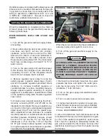
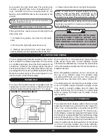
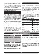
The integrated furnace control has provisions to
supply power and control an electronic air clean-
er rated at 120vac, 1.0 amp max. 120 volt power
will be available at these terminals whenever the
circulating fan is operating in the heating or cooling
modes.
18 - OPTIONAL ACCESSORIES (FIELD SUPPLIED/INSTALLED)
POWER HUMIDIFIER
The integrated furnace control has provisions to
supply power and control a line voltage humidi-
fier or the primary of a 120 / 24 volt humidifier step
down transformer, rated at 120vac, 1.0 amp max.
NOTE:
All HUM and EAC terminals are 120V. Do not di-
rectly connect 24V equipment to these terminals.
19 - STARTUP PROCEDURES
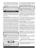
This furnace is equipped with a HSI (Hot Surface
Ignition) device. Each time that the room thermostat
calls for heat, the HSI lights the main burners di-
rectly. See the lighting instructions on the furnace.
TO START THE FURNACE
1. Remove the burner compartment access door.
2. Shut off the electrical power to the furnace and
set the room thermostat to its lowest setting.
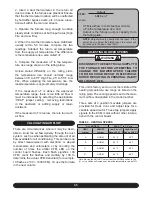
IMPORTANT:
Ensure that the manual gas con-
trol switch has been in the “OFF” position for at
least 5 minutes. Do not attempt to manually light
the main burners.
3. Turn the gas control switch to the “ON” position.
4. Replace the burner compartment access door.
5. Restore electrical power to the furnace.
6. Set the room thermostat to a point above room
temperature to light the furnace.
7. After the burners are lit, set the room thermostat
to the desired temperature.
TO SHUT DOWN THE FURNACE
1. Set the room thermostat to its lowest setting.
2. Remove the burner compartment access door.
3. Turn the gas control switch to the “OFF” position.
4. The furnace appliance shut-off valve may be
closed if desired.
5. Power to the furnace must remain on for the air
conditioner to work.
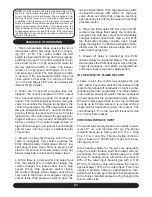
WARNING
SHOULD OVERHEATING OCCUR OR THE
GAS BURNERS FAIL TO SHUT OFF, CLOSE
THE MANUAL GAS VALVE FOR THE FUR-
NACE BEFORE SHUTTING OFF THE ELEC-
TRICAL POWER TO THE FURNACE. FAILURE
TO DO SO CAN CAUSE AN EXPLOSION OR
FIRE RESULTING IN PROPERTY DAMAGE,
PERSONAL INJURY OR LOSS OF LIFE.
BEFORE RESTARTING THE FURNACE,
CHECK ALL PLASTIC VENTS AND WIRES
FOR DAMAGE.
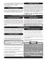
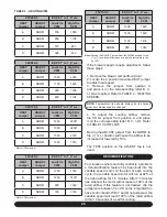
uous low heat operation. Once high heat is started
from automatic staging, the demand for high heat
remains until the heat call is satisfied.
* Factory Setting
TWO STAGE THERMOSTAT
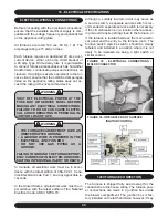
When connecting a two stage thermostat, the jump-
er (P5) must be in the “NONE” position. The control
runs high heat from the thermostat W2 demand.
THERMOSTAT LOCATION
The thermostat should be located approximately 5
feet above the floor, on an inside wall where there is
good natural air circulation, and where the thermostat
will be exposed to average room temperatures. Avoid
locations where the thermostat will be exposed to cold
drafts, heat from nearby lamps or appliances, expo-
sure to sunlight, heat from inside wall stacks, etc.
THERMOSTAT HEAT ANTICIPATOR SETTING:
0.1 AMP (Honeywell)


