23
!
!
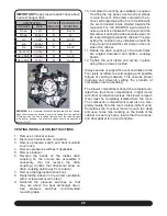
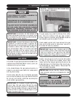
Do not locate the terminal on the side of the build-
ing facing the prevailing winter winds.
CAUTION
Improper location or installation can result in
structural damage to the building, damage to
the exterior finish of the building, or may al-
low recirculation or freezing of the flue gases
onto or into the combustion air intake.
Moisture in the flue gases condenses as
it leaves the terminals. This moisture can
freeze on exterior walls, soffits, and other
nearby objects. Some discoloration is to be
expected.
The vent terminal should be located no fewer than
6 feet from an inside corner formed by two exterior
walls. A 10 foot distance is recommended.
Recommended clearance for overhangs is a mini-
mum of 1 foot vertically for each foot horizontally
up to 6 feet.
Any adjacent painted surfaces should be in good con-
dition; no cracks, peeling paint, etc. If wooden sur-
faces that may be periodically exposed to flue gases
are present, consider treating with a sealer such as
Thompson’s Water Seal®. Additional information
about sealers may be obtained from the Thompson’s
web site at
www.thompsonsonline.com.
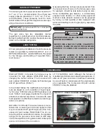
MULTIPLE VENTING
IMPORTANT:
When installing multiple furnaces
in close proximity, each requires dedicated com-
bustion air and exhaust venting.
COMMON VENTING IS PROHIBITED!!
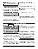
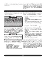
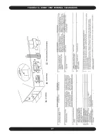
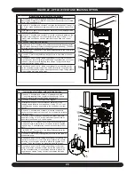
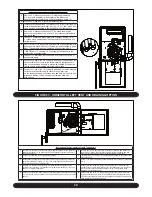
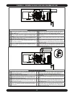
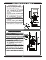
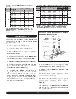
If two of these furnaces are to be installed in
close proximity, the combustion air intake and
exhaust terminations may be installed as shown
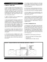
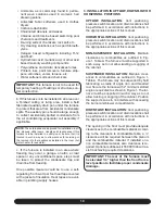
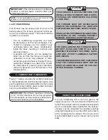
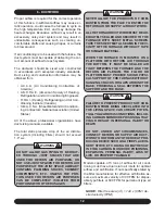
in Figures 12 and 13
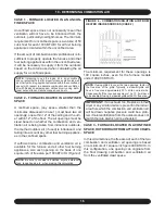
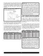
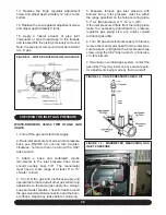
CONCENTRIC VENTING KIT
Concentric venting terminal kits may be used for
this series furnace. They provide a means of ob-
taining combustion air and exhausting products of
combustion utilizing a single penetration through
the exterior wall. This can be useful when there is
limited wall space available. Kits are available in
2” and 3” sizes. If venting the 60000 Btuh model
with 1½” vent material, and a concentric vent kit
is necessary, a increase coupling may be used to
connect to the 2” concentric venting kit. Read the
instructions supplied with the kit for additional in-
stallation instructions and details.
CONCENTRIC VENT TERMINATION
INSTALLATION INSTRUCTIONS
Follow the concentric vent termination manufac-
tures instructions for installation of the concentric
vent termination kit. These instructions can be
found by contacting the furnace manufacture. Fur-
nace manufacture contact information is found on
the front cover of this installation manual and oper-
ating instructions.
LOCATION
Avoid locating the terminals where the flue gas
could become stagnant and allow recirculation into
the combustion air intake.
Avoid locating the terminal in locations where drip-
ping condensate may cause problems such as
sidewalks, patios, above planters, near windows
where exhaust gases may cause fogging, etc.
Avoid locating the termination too close to shrubs
and other vegetation. The condensate may stunt or
kill them.
Caulk all cracks, seams or joints within a 6 foot ra-
dius of the termination.
Do not terminate under a deck unless there is ad-
equate clearance to prevent damage from the flue
gases. A termination may be located at the end of a
patio deck. Piping running beneath the deck must
be suitably insulated and suspended in a manner to
prevent condensate from collecting and freezing.

