13
!
!
!
!
IMPORTANT:
Some high efficiency filters have
a greater than normal resistance to airflow. This
can adversely affect furnace operation.
DUCTWORK STEPS
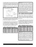
1. Position the furnace to minimize ductwork length
and fittings.
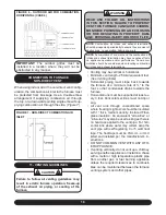
2. Cut open a return air inlet. The choices are fur-
nace bottom, either side, or any combination there-
of (i.e., two sides or a side and the bottom).
WARNING
DO NOT USE THE REAR PANEL AS A RE-
TURN AIR INLET. THERE IS INSUFFICIENT
ROOM TO PERMIT ADEQUATE AIRFLOW.
In all cases, cut the inlet air opening the full width
of the knockouts.
3. Connect the return air duct or filter fitting to the
furnace. The connection should be sealed air tight
to prevent entraining combustion gases from an ad-
jacent fuel burning appliance, or entraining combus-
tion air for this furnace or adjacent fuel burning ap-
pliances.
4. Ensure that there is adequate space and acces-
sibility for air filter removal.
NOTE:
If two return air inlets are used, both must be
equipped with filters.
5. If an air conditioning evaporator coil is required,
position it on the supply air side of the furnace. En-
sure that no air can bypass the evaporator coil.
6. Connect the supply air plenum to the supply air
outlet.
FLEXIBLE DUCT CONNECTORS
are an effective
device to prevent the telegraphing of mechanical
noise from the furnace to other parts of the home
via the ductwork. If using flexible connectors, ensure
that the adjoining duct is independently supported.
7 - VENTILATION AND COMBUSTION AIR
WARNING
READ, UNDERSTAND AND FOLLOW ALL IN-
STRUCTIONS IN THIS SECTION. FAILURE TO
PROPERLY VENT OR SUPPLY COMBUSTION
AIR TO THIS FURNACE CAN CAUSE CARBON
MONOXIDE POISONING, OR AN EXPLOSION
OR FIRE, RESULTING IN PROPERTY DAM-
AGE, PERSONAL INJURY OR LOSS OF LIFE.
DEFINITIONS
“Vent and Chimney”
refer to open passageways that
convey vent gasses from the furnace, or its vent
connector to the outside. Vents can be horizontal or
vertical. When they serve only one gas appliance,
they are called “dedicated” vents or chimneys.
When they serve multiple gas appliances, they are
called “common” vents or chimneys.
“Vent Connector”
refers to a pipe or duct that con-
nects the furnace to a vent or chimney. Vent con-
nectors usually run from the furnaces vent collar
to the vent or chimney. Vent connectors may have
vertical and horizontal runs.
“Venting System”
refers to a continuous open pas-
sageway from the vent collar to the outside. Vent-
ing systems usually have a vent connector(s) and a
vent or chimney. Venting systems commonly serve
a single furnace, or a single furnace and a hot water
heater. Other multiple appliance venting systems
are less common.
“Fan Assisted Combustion System”
refers to an appli-
ance equipped with an integral mechanical means to
either draw or force products of combustion through
the combustion chamber and/or heat exchanger. This
series furnace uses a draft inducer to draw combustion
products through the heat exchanger and is considered
to have a fan-assisted combustion system. Category
IV furnaces with fan-assisted combustion systems
must not be vented into single wall metal vents.
GENERAL CONSIDERATIONS
If this furnace is to replace a Category I type furnace
connected to a chimney serving other appliances,
steps must be taken to ensure that the remaining
appliances will vent properly after the removal of
the existing furnace. There is a probability that the
existing chimney will be too large.


