17
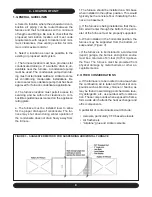
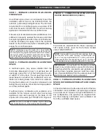
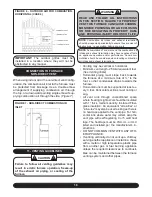
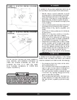
The other opening may communicate freely with a
ventilated the attic. If using the attic air, ensure that
the opening is ducted from the ceiling high enough
to be above the insulation. The attic must be ad-
equately vented with soffit vents or gable vents
(Figure 5)
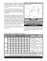
As an alternative to creating an opening in the floor to
draw air from a crawl space, a duct may be dropped
from the attic terminating 12” above the floor.
The following table shows minimum free areas and
round pipe sizes when drawing combustion air ver-
tically from the attic or crawl space for the furnace
only. If other fuel burning appliances are present,
their combustion air and ventilation air require-
ments must be added to those of the furnace.
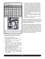
TABLE 2 - VERTICAL AIR SUPPLY (CASE 3)
Model
Free Area
Ea. Opening
Round Pipe Size
60
15 in.²
5 in.
80
20 in.²
6 in.
100
25 in.²
6 in.
120
30 in.²
7 in.
IMPORTANT:
If the attic has an exhaust fan
(power vent), it may create a negative pres-
sure sufficiently large enough to prevent the
attic from being an effective source of combus-
tion and ventilation air. Powered attic fans do
not customarily run during the heating season;
however, some are controlled by a humidistat as
well as a thermostat, which may allow some op-
eration during the heating season. The choices
are (a) use the direct vent option; (b) obtain out-
door air from elsewhere; or (c) interlock the attic
exhaust fan with the furnace such that the two
cannot operate simultaneously.
CASE 4: FURNACE LOCATED IN A CONFINED
SPACE, OUTDOOR AIR DUCTED HORIZONTALLY
Similar to Case 3, outdoor air for combustion and
ventilation may be drawn through horizontal duct-
ing. The free area for each opening is calculated on
the basis of a minimum of 1 square inch per 2000
BTU/Hr input.
The following table shows minimum free areas
and round pipe sizes when drawing combustion air
horizontally from the outdoors for the furnace only.
If other fuel burning appliances are present, their
combustion air and ventilation air requirements
must be added to those of the furnace.
TABLE 3 - HORIZONTAL AIR SUPPLY (CASE 4)
Model
Free Area
Ea. Opening
Round Pipe Size
60
30 in.²
7 in.
80
40 in.²
8 in.
100
50 in.²
8 in.
120
60 in.²
9 in.
IMPORTANT:
If grilles are used on the outside
wall, they must be sized properly. Most sidewall
grilles have only 50% free area. In the case of
a unit with 100,000 Btuh input, which requires a
pair of 8” round pipes to obtain sufficient com-
bustion and ventilation air, the duct could be an
equivalent rectangular duct; 8” x 7” for example.
Based on 50% free area for the inlet grilles, the
actual grille size would have to be 14” x 8” or its
equivalent. A transition may be used to reduce
to the smaller duct size if necessary.
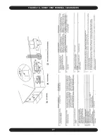
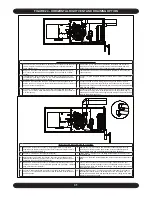
FIGURE 5 - OUTSIDE AIR FOR COMBUSTION, AT-
TIC OR CRAWL SPACE (CASE 3)

