24
Chapter 2
•
Configuration via Web UI
3500782-0001 Revision E
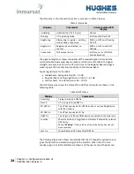
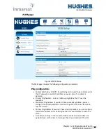
The status text in the
Connection
section is as shown in Table 3 below.
Table 3: Status bar
Display
Comments
Corresponding LED
display
Initializing
Initial startup (~15-20 secs)
Various
Pointing
UT in pointing mode
All three LEDs flash 1Hz
Registering
Attempting to register - pointing
mode exited or bypassed
PWR on, GPS on or flashing,
NET off
Registered
Registered and attached, no
context
PWR on, GPS on and NET
flashing
Connected
PDP context active
All three on (or off after 1
minute timeout)
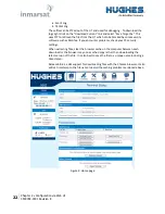
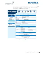
The signal strength bar shows the quality of the received signal. It also lists the
current satellite beam type, beam number and the current satellite. The signal
strength increases in value as the UT transitions to the Regional Beam and again
when it gets a PDP context and transitions to the Narrow Beam.
Typical signal levels for the 9502:
•
Global beam, during pointing: 50
–
55 dB
•
Regional beam, during registration or idle: 57
–
61 dB
•
Narrow beam, on a data channel: 65
–
70 dB
The
GPS
status area shows the status of the GPS fix and results are shown in the
following table:
Table 4: GPS status
Display
Comments
Acquiring
Trying to acquire a GPS fix
Stored
UT is using a Stored GPS fix
2D GPS Fix
The UT has acquired a 2D GPS fix and can continue Registration
with the network
3D GPS Fix
The UT has acquired a 3D Fix
GNSS Fix
The UT got a fix from a GNSS device connected to the serial port.
Location
Shows Latitude and Longitude coordinates if allowed by network
GPS Policy.
Shows “
Waiting
” if the unit has a fix but the policy has not yet
been received.
Last Fix
Shows date and UTC time of last GPS fix.
The
Pointing Info
section shows the satellite that the UT should be pointed to and
gives the Azimuth and elevation angles to the satellite. When the UT is in an
overlap region, all visible satellites are shown and the user can pick the best one.

