7 What you need to know about SmartWire-DT®
7.4 Cyclical input and output data of the SWD modules
64
SmartWire-DT Gateway EU5C-SWD-DP
01/13 MN120001Z-EN
www.eaton.eu
7.4 Cyclical input and output data of the SWD modules
All the inputs and outputs of the SWD modules that are present are stored in
a data storage area inside the SWD coordinator. This data storage area is
referred to as the "process image. " The input data can have a maximum size
of 800 bytes, while the output data can have a maximum size of 642 bytes.
In total, the data area must not exceed 1000 bytes. The cyclic exchange of
data between the SWD coordinator and the SWD modules takes place in a
common data frame.The input data can consist of several bytes, depending
on the module. This input data contains information such as switch positions
and diagnostic information.
The modules' input and output data is available to the PLC programming
environment. To find out more about how it can be accessed, please refer to
Chapter 5 "Take XSoft-CoDeSys-2 into operation“, page 31 and
Chapter 6 "Take STEP 7 into operation“, page 42 .
Diagnostics possibilities
The SWD coordinator can provide the following diagnostic information:
•
Cyclic diagnostic information
•
Extended diagnostics information
Cyclic diagnostics information
SmartWire-DT provides you with cyclical diagnostic information. This infor-
mation can be evaluated in the program and used for further control tasks.
This basic diagnostic information is coded in the normal process image of
each SWD module. The information about whether the SWD module is
exchanging data normally or whether diagnostic alarms are currently present
is provided on all SWD modules in the first input byte (byte 0) at bit positions
4 and 6.
Example of input and diagnostic data
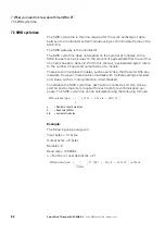
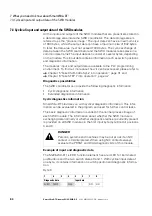
The M22-SWD-K11-LED-R function element has a red LED for illuminated
pushbuttons and the two switch states 0 and 1. With cyclical input data of
one byte, it contains information on switch position and diagnostic informa-
tion.
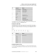
Byte 0:
DANGER
Persons, systems and machines may be put at risk if an N/C
contact is misinterpreted. When using N/C contacts always
evaluate the PRSNT and DIAG diagnostic bits of this module.
7
6
5
4
3
2
1
0
Diagnostic data
Input data
SUBST
PRSNT
–
DIAG
–
–
NO1
NC1


