6 Parameter structure
6.6 Parameter
DC1-S…20…, DC1-S…OE1 Variable Frequency Drives
05/21 MN040058EN
www.eaton.com
145
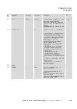
6.6.2 “Basic” parameter group
Table 48: “Basic” parameter group
Para-
meter
Designation
min. value
max. value
Description
DS
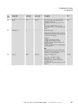
P-01
Max Frequency
0.0 Hz
5 x P-09
Sets the upper limit for the speed of the motor.
This can be set to any value between “f-min” and
5x the “motor nom frequency”. When “Motor Nom
Frequency” (P-09) is changed, P-01 is set to the
value of P-09.
”Motor Nom Speed” (P-10) = 0, the maximum
speed limit will be displayed in Hz.
”Motor Nom Speed” (P-10) > 0, the maximum
speed limit will be displayed in rpm.
50.0 hz
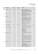
P-02
Min Frequency
0.0 Hz
P-01
Sets the lower limit for the speed of the motor
This can be set to any value between 0 and
“f-max” (P-01).
This can be set to any value between 0 and
“f-max” (P-01). When “Motor Nom Frequency”
(P-09) is changed, P-01 is set to zero.
“Motor Nom Speed” (P-10) = 0, the minimum
speed limit will be displayed in Hz.
”Motor Nom Speed” (P-10) > 0, the minimum
speed limit will be displayed in rpm.
0.0 Hz
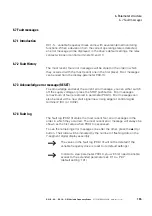
P-03
t-acc
0.00 s
600 s
Sets the acceleration ramp time in seconds.
The time interval set in P-03 represents the time
taken to accelerate from zero to “Motor Nom
Frequency” (P-09).
5.0 s
P-04
t-dec
0.00 s
600 s
Sets the deceleration ramp time in seconds.
The time interval set in P-04 represents the time
taken to decelerate from “Motor Nom Frequency”
(P-09) to zero.
5.0 s
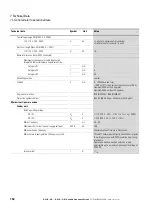
P-05
Stop Mode
0
2
Determines the action taken by the drive in the
event of the drive enable signal being removed.
0: Ramping. When the enable signal is removed,
the drive will ramp to stop, with the rate controlled
by “t-dec” (P-04).
1: Coasting. When the enable signal is removed,
the drive output is immediately disabled, and the
motor will coast (freewheel) to stop.
2: Ramping. When the enable signal is removed,
the drive will ramp to stop, with the rate controlled
by “t-dec” (P-04). If the mains supply is lost the
drive will ramp to stop using the deceleration ramp
set by P-24. Condition: P-24 is set to a time which
is shorter than the one for discharging the DC link.
Otherwise the drive will trip due to “under
voltage”.
1
Summary of Contents for PowerXL
Page 4: ......

