background image

EATON

Powerware

®

9355 Parallel UPS (10/15 kVA) User’s Guide

S

164201601 Rev A

www.powerware.com

i

Table of Contents

1

Introduction

1

. . . . . . . . . . . . . . . . . . . . . . . . . . . . . . . . . . . . . . . . . . . . . . . . . . . . . . . . .

2

Safety Warnings

3

. . . . . . . . . . . . . . . . . . . . . . . . . . . . . . . . . . . . . . . . . . . . . . . . . . . . .

3

UPS Setup

7

. . . . . . . . . . . . . . . . . . . . . . . . . . . . . . . . . . . . . . . . . . . . . . . . . . . . . . . . . .
Inspecting the Equipment

7

. . . . . . . . . . . . . . . . . . . . . . . . . . . . . . . . . . . . . . . . . . . . . . . . . . . . . . . . . . . . . . . .

Floor Loading

8

. . . . . . . . . . . . . . . . . . . . . . . . . . . . . . . . . . . . . . . . . . . . . . . . . . . . . . . . . . . . . . . . . . . . . . . .

Clearances

8

. . . . . . . . . . . . . . . . . . . . . . . . . . . . . . . . . . . . . . . . . . . . . . . . . . . . . . . . . . . . . . . . . . . . . . . . . .

Unloading the Cabinet(s)

9

. . . . . . . . . . . . . . . . . . . . . . . . . . . . . . . . . . . . . . . . . . . . . . . . . . . . . . . . . . . . . . . .

Three-High Cabinets or Two-High EBMs

9

. . . . . . . . . . . . . . . . . . . . . . . . . . . . . . . . . . . . . . . . . . . . . . . . . . .

Two-High UPS Cabinets

13

. . . . . . . . . . . . . . . . . . . . . . . . . . . . . . . . . . . . . . . . . . . . . . . . . . . . . . . . . . . . . .

4

Parallel Installation

17

. . . . . . . . . . . . . . . . . . . . . . . . . . . . . . . . . . . . . . . . . . . . . . . . . . .

5

Installing Options

27

. . . . . . . . . . . . . . . . . . . . . . . . . . . . . . . . . . . . . . . . . . . . . . . . . . . .

Powerware Hot Sync CAN Bridge Card

28

. . . . . . . . . . . . . . . . . . . . . . . . . . . . . . . . . . . . . . . . . . . . . . . . . . . . . .

6

Stabilizing the Cabinet

33

. . . . . . . . . . . . . . . . . . . . . . . . . . . . . . . . . . . . . . . . . . . . . . . .

7

Extended Battery Module Installation

37

. . . . . . . . . . . . . . . . . . . . . . . . . . . . . . . . . . . . .

8

Operation

41

. . . . . . . . . . . . . . . . . . . . . . . . . . . . . . . . . . . . . . . . . . . . . . . . . . . . . . . . . . .

Control Panel Functions

41

. . . . . . . . . . . . . . . . . . . . . . . . . . . . . . . . . . . . . . . . . . . . . . . . . . . . . . . . . . . . . . . . .

Changing the Language

42

. . . . . . . . . . . . . . . . . . . . . . . . . . . . . . . . . . . . . . . . . . . . . . . . . . . . . . . . . . . . . .

Display Functions

42

. . . . . . . . . . . . . . . . . . . . . . . . . . . . . . . . . . . . . . . . . . . . . . . . . . . . . . . . . . . . . . . . . . .

User Settings

44

. . . . . . . . . . . . . . . . . . . . . . . . . . . . . . . . . . . . . . . . . . . . . . . . . . . . . . . . . . . . . . . . . . . . . .

Initial Startup

46

. . . . . . . . . . . . . . . . . . . . . . . . . . . . . . . . . . . . . . . . . . . . . . . . . . . . . . . . . . . . . . . . . . . . . . . .

Configuring the UPS for EBMs

47

. . . . . . . . . . . . . . . . . . . . . . . . . . . . . . . . . . . . . . . . . . . . . . . . . . . . . . . . . . . .

Parallel System Shutdown

48

. . . . . . . . . . . . . . . . . . . . . . . . . . . . . . . . . . . . . . . . . . . . . . . . . . . . . . . . . . . . . . .

Individual UPS Shutdown

49

. . . . . . . . . . . . . . . . . . . . . . . . . . . . . . . . . . . . . . . . . . . . . . . . . . . . . . . . . . . . . . . .

Restarting the Parallel System

50

. . . . . . . . . . . . . . . . . . . . . . . . . . . . . . . . . . . . . . . . . . . . . . . . . . . . . . . . . . . .

9

Parallel Bypass

51

. . . . . . . . . . . . . . . . . . . . . . . . . . . . . . . . . . . . . . . . . . . . . . . . . . . . . .

10 Troubleshooting

53

. . . . . . . . . . . . . . . . . . . . . . . . . . . . . . . . . . . . . . . . . . . . . . . . . . . . . .

Typical Alarms and Conditions

53

. . . . . . . . . . . . . . . . . . . . . . . . . . . . . . . . . . . . . . . . . . . . . . . . . . . . . . . . . . . .

Silencing the Alarm

55

. . . . . . . . . . . . . . . . . . . . . . . . . . . . . . . . . . . . . . . . . . . . . . . . . . . . . . . . . . . . . . . . . . . .

Service and Support

56

. . . . . . . . . . . . . . . . . . . . . . . . . . . . . . . . . . . . . . . . . . . . . . . . . . . . . . . . . . . . . . . . . . .

Summary of Contents for Powerware 9355 Parallel

Page 1: ...Powerware 9355 Parallel UPS 10 15 kVA User s Guide...

Page 2: ...sing Equipment meets all requirements of the Canadian Interference Causing Equipment Regulations ICES 003 Cet appareil num rique de la classe A respecte toutes les exigences du Reglement sur le mat ri...

Page 3: ...quipment designed for use within certain voltage limits 93 68 EEC Amending Directive 73 23 EEC 89 336 EEC Council Directive relating to electromagnetic compatibility 92 31 EEC Amending Directive 89 33...

Page 4: ...nstructions This symbol indicates that you should not discard the UPS or the UPS batteries in the trash This product contains sealed lead acid batteries and must be disposed of properly For more infor...

Page 5: ...el Installation 17 5 Installing Options 27 Powerware Hot Sync CAN Bridge Card 28 6 Stabilizing the Cabinet 33 7 Extended Battery Module Installation 37 8 Operation 41 Control Panel Functions 41 Changi...

Page 6: ...TABLE OF CONTENTS EATON Powerware 9355 Parallel UPS 10 15 kVA User s Guide S 164201601 Rev A www powerware com ii...

Page 7: ...onfiguration In addition when one UPS is taken out of service for maintenance or is not operating properly a redundant UPS continues to supply uninterrupted power to the critical load A parallel Power...

Page 8: ...INTRODUCTION EATON Powerware 9355 Parallel UPS 10 15 kVA User s Guide S 164201601 Rev A www powerware com 2...

Page 9: ...ectric shock install this UPS in a temperature and humidity controlled indoor environment free of conductive contaminants Ambient temperature must not exceed 40 C 104 F Do not operate near water or ex...

Page 10: ...eur uniquement l int rieur dans un lieu d pourvu de mat riaux conducteurs o la temp rature et l humidit ambiantes sont contr l es La temp rature ambiante ne doit pas d passer 40 C Ne pas utiliser prox...

Page 11: ...l riesgo de incendio o de choque el ctrico instale este SIE en un lugar cubierto con temperatura y humedad controladas libre de contaminantes conductores La temperatura ambiente no debe exceder los 40...

Page 12: ...SAFETY WARNINGS EATON Powerware 9355 Parallel UPS 10 15 kVA User s Guide S 164201601 Rev A www powerware com 6...

Page 13: ...g the Equipment If any equipment has been damaged during shipment keep the shipping and packing materials for the carrier or place of purchase and file a claim for shipping damage If you discover dama...

Page 14: ...proximate weights are shown in the following table Standard Model Floor Loadings 2 High 3 High Cabinets Powerware 9355 Maximum Weight Point Loading lb in2 kg cm2 2 High UPS 381 lb 173 kg 95 6 7 3 High...

Page 15: ...y see page 8 Unloading the cabinets requires at least two people to safely remove the cabinets from the pallet To unload three high cabinets or two high EBMs continue to the following section To unloa...

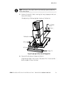
Page 16: ...Retain the hardware for later use NOTE Be sure to retain the stabilizing bracket and hardware for later re assembly onto the cabinet 3 Remove the front cover from the bottom cabinet to access the fron...

Page 17: ...emove the two M10 bolts securing the front shipping bracket and remove the bracket If needed adjust the leveling feet to release the bracket Stabilizing Bracket Front Shipping Bracket Shipping Pad M4...

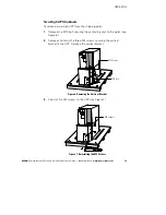
Page 18: ...ly roll the cabinet toward the rear of the pallet Once the pallet tilts continue rolling the cabinet down the pallet until the cabinet touches the floor see Figure 4 If needed adjust the leveling feet...

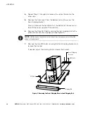
Page 19: ...e shipping pallet 1 Remove the M10 bolt securing the vertical bracket to the pallet see Figure 6 2 Remove and retain the three M4 screws securing the vertical bracket to the UPS Remove the vertical br...

Page 20: ...d then lift the cover up and off the cabinet 6 Remove the three M10 bolts securing the rear shipping pad to the pallet and remove the shipping pad see Figure 8 NOTE Hold the back of the cabinet so tha...

Page 21: ...r the bottom edge and snap into place NOTE Be sure to support the front and back of the cabinet when rolling it off the pallet to prevent tipping 9 Slowly roll the cabinet toward the rear of the palle...

Page 22: ...allel UPS 10 15 kVA User s Guide S 164201601 Rev A www powerware com 16 10 With the cabinet supported slowly pull the pallet away from the cabinet see Figure 10 Figure 10 Removing the Pallet 11 Roll t...

Page 23: ...personnel such as a licensed electrician should perform the UPS installation and initial startup Risk of electrical shock To hardwire the parallel system 1 Verify that the electrical connections to th...

Page 24: ...m 18 4 Determine your equipment s grounding requirements according to your local electrical code 5 Remove the parallel tie cabinet front cover see Figure 11 Figure 11 Parallel Tie Cabinet Front Cover...

Page 25: ...the parallel bypass breaker is in the OFF position see Figure 13 9 Mount the parallel tie cabinet to the wall and install the conduit Figure 13 Parallel Bypass Breaker 10 Verify that each UPS battery...

Page 26: ...ALLATION EATON Powerware 9355 Parallel UPS 10 15 kVA User s Guide S 164201601 Rev A www powerware com 20 Battery Circuit Breaker UPS Wiring Access Cover Conduit Landing Plates Figure 14 UPS Rear View...

Page 27: ...Number of Conduits 208 Input 60A 4 AWG 10 AWG 120 lb in 1 25 conduit 1 220 p 60A 4 AWG 10 AWG 120 lb in 13 5 Nm 1 25 conduit 1 208 Output 6 AWG 10 AWG 120 lb in 1 00 d i 1 220 p 6 AWG 10 AWG 120 lb in...

Page 28: ...1 Rev A www powerware com 22 Ground Maintenance Bypass Contacts TB2 Figure 15 UPS Terminal Block 3 High Shown 14 Hardwire the output terminations from the UPS to the parallel tie cabinet see Figure 16...

Page 29: ...ires in the parallel tie cabinet see Figure 15 Connect the black and the red wire to TB2 on the UPS Cap the blue wire NOTE The maintenance bypass contacts are normally open To ensure proper bypass ope...

Page 30: ...he AC input to the bypass breaker see Figure 18 Line 1 Line 2 Line 3 Figure 18 Bypass AC Input Wiring 20 Verify the phase rotation for each UPS and the bypass input 21 Reinstall the internal cover rem...

Page 31: ...01 Rev A www powerware com 25 From UPS 4 Output From UPS 3 Output From UPS 2 Output Red Wire open when breaker is open Bypass Input Black Wire common From UPS 1 Output 225A 80A 4X LOAD Blue Wire close...

Page 32: ...PARALLEL INSTALLATION EATON Powerware 9355 Parallel UPS 10 15 kVA User s Guide S 164201601 Rev A www powerware com 26 Figure 20 Parallel UPS Schematic...

Page 33: ...emergency power off REPO relay output contacts or programmable signal inputs refer to the Powerware 9355 UPS 10 15 kVA User s Guide Figure 21 shows the location of the communication options and contro...

Page 34: ...ivity for operational mode control and metering of a parallel system at any UPS in the system Plug In Terminal Block Figure 22 Powerware Hot Sync CAN Bridge Card To install the Powerware Hot Sync CAN...

Page 35: ...isted pair on all cards together 4 Wire the factory installed pull chain wiring to Signal Input 2 on each UPS and daisy chain the wiring to each UPS as shown in Figure 24 Be sure to check correct pola...

Page 36: ...re 9355 Parallel UPS 10 15 kVA User s Guide S 164201601 Rev A www powerware com 30 SHIELD CAN H CAN L TX TX 10 9 8 1 7 6 5 4 3 2 NO COM NC ALM RTN ALARM J3 J5 1 2 1 2 1 2 1 2 UPS 1 UPS 2 UPS 3 UPS 4 F...

Page 37: ...the bottom cover and also the middle cover if 3 high remove a knockout tab in the top edge of the cover for each cable With wire cutters cut either side of the tab and twist down to remove the tab se...

Page 38: ...vers starting with the bottom cabinet see Figure 26 Hang the top edge of the cover on the cabinet first then lower the bottom edge and snap into place Be sure the cables fit in the access holes in the...

Page 39: ...t 2 Attach the stabilizing bracket to the bottom of the cabinet rear panel using the retained hardware from the shipping pallet according to the cabinet configuration S For one cabinet see Figure 28 S...

Page 40: ...ABINET EATON Powerware 9355 Parallel UPS 10 15 kVA User s Guide S 164201601 Rev A www powerware com 34 M4 Screws Figure 28 Stabilizing Bracket with One Cabinet M4 Screws Figure 29 Stabilizing Bracket...

Page 41: ...STABILIZING THE CABINET EATON Powerware 9355 Parallel UPS 10 15 kVA User s Guide S 164201601 Rev A www powerware com 35 M4 Screws Figure 30 Stabilizing Bracket with Three Cabinets...

Page 42: ...STABILIZING THE CABINET EATON Powerware 9355 Parallel UPS 10 15 kVA User s Guide S 164201601 Rev A www powerware com 36...

Page 43: ...In a parallel system each UPS should have the same number of Extended Battery Modules EBMs to ensure equivalent runtimes To install the optional EBM 1 Position the EBM adjacent to the next cabinet 2 V...

Page 44: ...arallel UPS 10 15 kVA User s Guide S 164201601 Rev A www powerware com 38 UPS Battery Connector Rear Ground Strap EBM Battery Circuit Breaker EBM Battery Connector EBM Cable UPS Battery Circuit Breake...

Page 45: ...et 9 Install the remaining ground straps between each cabinet see Figure 32 10 Reinstall the top front covers removed in Step 8 Hang the top edge of the cover on the cabinet first then lower the botto...

Page 46: ...EXTENDED BATTERY MODULE INSTALLATION EATON Powerware 9355 Parallel UPS 10 15 kVA User s Guide S 164201601 Rev A www powerware com 40...

Page 47: ...hutdown and configuring the UPS for Extended Battery Modules EBMs Control Panel Functions The UPS has a four button graphical LCD with backlight It provides useful information about the UPS itself loa...

Page 48: ...alarm condition See Troubleshooting on page 53 for additional information Changing the Language Press and hold the first button on the left for approximately five seconds to select the language menu...

Page 49: ...r Output L N and L L Current Frequency Power Battery Voltage Current Runtime Input L N and L L Current Frequency Bypass L N and L L Frequency Control Go to Bypass Mode Transfers the UPS system to inte...

Page 50: ...lish Elegir idioma Espa ol English Set NominalOutput Voltage Output 120V 208V 127V 220V 120V 208V Relay Config Relay Alarm 1 X Slot 1 1 2 3 4 or X Slot 2 1 2 3 4 Setup Battery Low On Battery On Bypass...

Page 51: ...UPS 32 models 4 strings for UPS 64 models Battery Capacity 1 through 65535 watts per cell 34 W cell Battery Low Alarm Level 1 750 through 1 950 volts per cell 1 880 V cell Bypass Voltage High Limit 1...

Page 52: ...sabled Enabled Reset Custom Event Settings 0 through 32 Total 0 32 Auto Output Configuration Enabled Disabled Enabled for initial startup Disabled after initial startup Initial Startup Startup and ope...

Page 53: ...Press the button twice to select the User Settings menu 4 Using the button scroll to the Number of Battery Strings option and press the button 5 Use the or buttons to select the number of strings acc...

Page 54: ...anel display and then press the button to select the TURN UPS ON OFF menu 3 Press the button to select the System Off option press the button 4 Confirm the selection Press and hold the button for thre...

Page 55: ...button 4 Confirm the selection Press and hold the button for three seconds until the UPS stops beeping The input contactor opens 5 Switch the UPS battery circuit breaker to the OFF position The UPS i...

Page 56: ...parallel tie cabinet to the ON position 6 Verify that no alarms appear on the UPS front panel display If the indicator is flashing do not proceed until all alarms are clear Check the UPS status from...

Page 57: ...to internal Bypass mode S Using the button on the front panel display scroll to the Control menu option and press the button S Press the button to select the Go to Bypass Mode option The and indicato...

Page 58: ...t internal bypass to return the parallel system to Normal mode 3 Set the system to internal Bypass mode S Using the button on the front panel display scroll to the Control menu option and press the bu...

Page 59: ...every second A utility failure has occurred and the UPS is in Battery mode The UPS is powering the equipment with battery power Prepare your equipment for shutdown Battery Low LED is on Continuous be...

Page 60: ...nstalled the input circuit breaker is off Verify that the isolation transformer input circuit breaker is on The remote emergency power off REPO switch is active or the REPO connector is missing Reset...

Page 61: ...bnormal output voltage at startup The UPS breaker on the parallel tie cabinet was not switched to the ON position properly Shut down the UPS where the alarm is indicated Switch the UPS breaker on the...

Page 62: ...llowing telephone numbers and ask for a UPS technical representative United States 1 800 843 9433 or 1 919 870 3028 Canada 1 800 461 9166 ext 260 All other countries Call your local service representa...

Reviews: