


EATON
Powerware
®
9355 Parallel UPS (10/15 kVA) User’s Guide
S
164201601 Rev A
www.powerware.com
17
Chapter 4
Parallel Installation
The Powerware 9355 has the following power connections:
S
3-phase (L1, L2, and L3), neutral, and ground connection for
rectifier/bypass input
S
3-phase (L1, L2, and L3), neutral, and ground connection for load
output
The nominal input/output voltages are:
S
120/208 or 127/220 Vac
Output overcurrent protection and disconnect switch must be provided
by others.
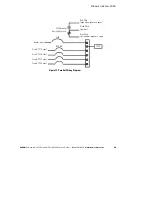
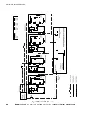
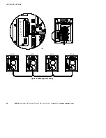
Figure 19 and Figure 20 beginning on page 25 show the oneline
diagrams.
W A R N I N G
Only qualified service personnel (such as a licensed electrician) should perform the UPS
installation and initial startup. Risk of electrical shock.
To hardwire the parallel system:
1.
Verify that the electrical connections to the installation site have
been properly installed.
2.
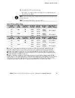
A wall-mounted, user-supplied, readily-accessible disconnection
device must be incorporated in the input wiring.
Compare the circuit breaker ratings to the ones in Table 1 on
page 21.
NOTE
To accommodate the feature of easy system expandability, it is recommended that
initial installation of the Powerware 9355 UPS contain wiring to support the maximum
capacity of the UPS cabinet.
3.
Switch off utility power to the distribution point where the parallel
tie cabinet and UPSs will be connected. Be absolutely sure there is
no power.


