background image

13

XSTORAGE HOME POWER METERS MANUAL

   MN700001EN   March 2019   www.eaton.com/xstorage

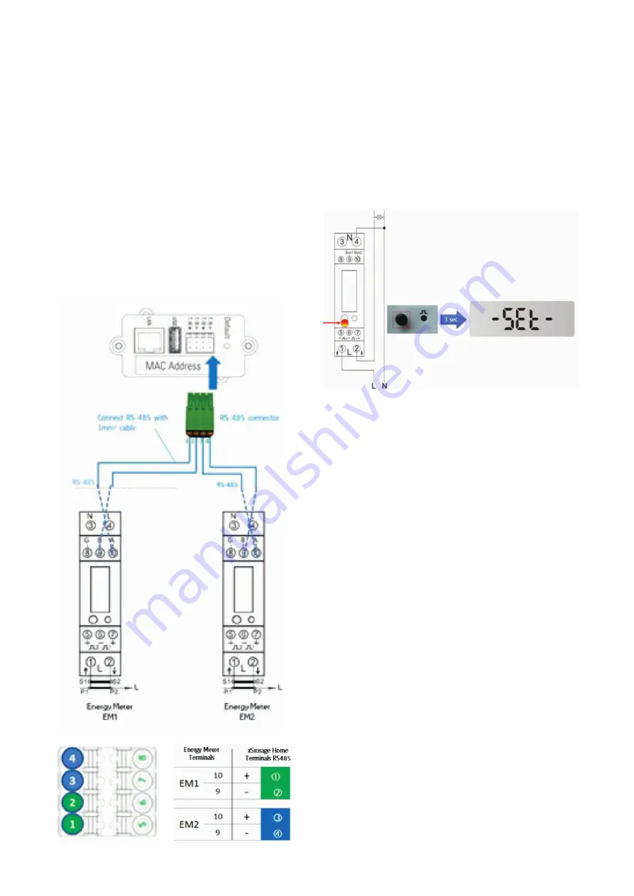
Figure 26 shows how to wire the power meter to the RS-485 

port of the communication card located on the lateral surface 

of the hybrid inverter. This enables the Modbus functionality. 

There are two power meters: power meter 1 (EM1) measures 

the AC power injected from the grid to power up the non-

critical loads and power meter 2 (EM2) measures the AC 

power generated from the existing PV system. The energy 

meter is connected to the terminal RS485 of the xStorage 

Home system with a 1 mm

2

 cable.

• 

EM2: Please wire the terminal (10) of the EM2 to the 

terminal (3) of the RS-485 port. Please wire the terminal (9) 

of the EM2 to the terminal (4) of the RS-485 port.

• 

EM1: Please wire the terminal (10) of the EM1 to the 

terminal (1) of the RS-485 port. Please wire the terminal 

(9) of the EM1 to the terminal (2) of the RS-485 port. EM1 

should be wired after the configuration is finalized.

Figure 26: How to wire the Eastron meters EM1 and EM2 to 

the RS-485 port of xStorage Home

To finalize the set-up of the power meter it is important that 

the appropriate meter is selected from the user interface. The 

procedure starts with EM2 and then needs to be repeated 

for EM1. Please refer to the xStorage Home user interface 

onboarding process manual to setup the meter in the user 

interface.
Please hold the button for three seconds, the meter will get 

into set-up mode as it is displayed in the picture below.

Figure 27: Set-up mode of the power meter

Once the meter is on SET mode as described, please be sure 

that from the user interface the right power meter is selected. 

The addressing between the power meter and xStorage Home 

is automatically made and the auto configuration is finished. 

Please refer to the user interface onboarding process manual 

to setup the meter in the user interface.
It is possible to verify that the process is successfully finalized 

also from the energy power meter display.
For the second power meter EM1 repeat all the steps 

previously made for the power meter EM2. Please note that 

it is only possible to setup EM1 after finalizing the installation 

of EM2. This means that the Eastron power meters are in SET 

status one at a time. If both meters are in SET mode during 

the installation, then addressing issues will occur. Follow 

the onboarding process of the user interface to finalize the 

installation of the power meters. 

Summary of Contents for Eastron SDM120CT

Page 1: ...xStorage Home Power Meters Manual For 4 2 kWh 6 kWh and 10 kWh systems capacity This document is intended for Eaton certified installers xStorage Home...

Page 2: ...know 3 3 SFERE DDS1946 DS Technical specifications installation and wiring 4 4 SFERE DTS1946 DS Technical specifications installation and wiring 8 5 Eastron SDM120CT Technical specifications installat...

Page 3: ...ustomer service we provide all specifications contained in this document are subject to change with due notice All drawings descriptions or illustrations contained in this document serve to provide a...

Page 4: ...nterface 2 the energy pulse indication light 3 the menu navigation keys 4 the model number Figure 3 SFERE DDS1946 DS product dimensions Figure 4 DIN rail mounting style overview Figure 5 Terminal wiri...

Page 5: ...UI to record the event history and to display the current energy consumption of both the critical and non critical loads as well as to track the PV generated energy as applicable The general wiring of...

Page 6: ...r both power meters with the exception of their assigned addresses Enter the programming mode as described 1 Power up the meter and irrespective of the measurement message displayed see display exampl...

Page 7: ...interface Please follow the instructions provided in the complementary xStorage Home user interface onboarding process manual 6 Again press to enter the third level menu This will display the default...

Page 8: ...re required The meter connection terminals must be directly connected to the L1 L2 L3 lines and N neutral wires Figure 16 L1 L2 L3 and N left side in the diagram is the side connected to the xStorage...

Page 9: ...id inverter The wiring of the RS 485 port terminals of the hybrid inverter and the power meters terminals is illustrated in Figure 19 Connect the RS 485 terminals of the power meter to the RS 485 term...

Page 10: ...ensure the activation of the correct measuring mode and the correct communications flow to the xStorage Home system i e to its hybrid inverter unit The following illustrations explain the communicatio...

Page 11: ...ied data and return to second level menu or b and at the same time to cancel the data modification and return to the second level menu 9 Press and to return to the first level menu i e the communicati...

Page 12: ...mpact electrical distribution box Figure 24 Figure 24 DIN Rail mount for Eastron meter During the installation of the power meter no additional protective devices are required The meter connection ter...

Page 13: ...appropriate meter is selected from the user interface The procedure starts with EM2 and then needs to be repeated for EM1 Please refer to the xStorage Home user interface onboarding process manual to...

Page 14: ...he power meter no additional protective devices are required The meter connection terminals must be directly connected to the L1 L2 L3 lines and N neutral wires The split core CT is installed on the L...

Page 15: ...r the correct password default 1000 before processing From the set up menu use the M and P buttons to select Address ID Press the Enter button to enter the selection routine The current setting will b...

Page 16: ...e la Longeraie 7 1110 Morges Switzerland Eaton com xstorage 2019 Eaton All Rights Reserved Publication No MN700001EN CSSC 1503 March 2019 Eaton is a registered trademark All other trademarks are prope...

Reviews: