


100
INSTALLATION AND OPERATION MANUAL
25-16328-B November 2020 www.eaton.com
Section 4: Appendix
Shop monitor unit wiring (MSU840)
Installation
1 . Separate the two halves of the unit
2 . Drill out (or knock out) the required cable entries in the surface mounting back
- box
3 . Fit the back-box in position and pass the wires into it
4 . Connect the unit according to the diagram below
ote:
N
No addressing of the interface is required . See control panel
operation for details
Standard connections
ote:
N
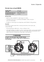
1 . This unit can only be used with CDB300/I detector base and compatible detectors
2 . Only connect cable screen to its adjacent earth terminal
3 . The end of line resistor must always be fitted, even if the spur is unused
4 . Maximum spur length - See BS5839 Pt1:2002 for Zone Coverage
5 . Maximum number of call points allowed is unlimited
6 . Detector zone end of line device is EOLM-1
7 . Callpoint zone has end of line resistor
EE
LLOOOOPP
OOUUTT
IIN
N
CCAALLLL
PPOOIIN
NTT
ZZOON
NEE
DDEETTEECCTTOORR ZZOON
NEE
SSOOUUN
NDDEERR
EEXXTTEERRN
NAALL
PPSSUU
M
MOON
NIITTOORR
2244VV
EEXXTTEERRN
NAALL
PPSSUU
IINNPPUUTT
11
22
FFIIRREE
RREELLAAYY
EE
EE
EE
EE
EE
N
N//OO
FFaauulltt
CCoonnttaacctt
N
N//OO
2244VV DDCC OOUUTTPPUUTT
PPOOW
WEERR SSUUPPPPLLYY UUN
NIITT
2244VV
OO//PP
CC N
N//CC
--
--
--
--
++
++
++
++
+
++
--
--
++
++
++
++
--
--
--
--
-- OOUUTT ++
-- IIN
N ++
-- OOUUTT ++
-- IIN
N ++
66KK88
1122KK
1122KK
12K
EEOOLLM
M--11
Analogue Addressable Loop
Callpoints can be connected with detectors
on detector zone if preferred


