Section X
Installation of Hose Assemblies
EATON
Aerospace Group
TF100-63B October 2018
15
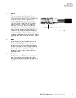
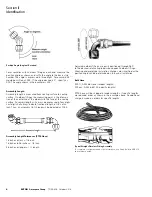
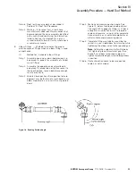
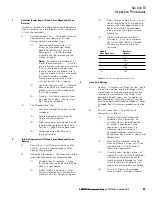
Figure 22. Routing and Clamping of Hose Lines
1.
Installation, General
Extra care should be exercised to avoid kinking
as a result of sharp bending or twisting.
Caution:
Kinking occurs more easily in larger
size hose and in very short hose lines. Use
care in handling and installing all PTFE lines.
Note:
Wires and clamps used to hold pre-
formed shapes should be removed at time of
installation.
2.
Routing And Clamping
All hose lines must be carefully routed and
securely clamped to avoid abrasion and particu-
larly to prevent kinking on flexing installations.
Figure 22 illustrates routing and clamping of
hose lines.
A.
Protection Against Abrasion — Eliminate
chafing against structure, moving parts
of other lines by proper clamping and
by use of chafing guard on unsleeved
hose assemblies (Aeroquip 656 PTFE
Guard or 646 Neoprene Chafe Guard), if
necessary.
B.
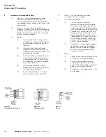
Hose Line Support — Support hose at
least every 24 inches. Closer supports
are preferred. Flexible liens should
be supported so that they will not
cause deflection of rigid connecting
lines. Hose lines between two rigid
connections may have excessive motion
restrained where necessary but should
never be rigidly supported. Support
clamps shall not restrict travel or
cause hose to be subjected to tension,
torsion, compression or shear stress
during flexing cycles. Select proper size
support clamp from Table VI.
Hose Dash Size
-4
-6
-8
-10
-12
High Pressure AE246
MS21919-
6
8
10
12
14
High Pressure AE246
with AE102 Fire Sleeve
MS21919-
11
14
16
17
19
Note:
Appropriate clamp cushion material to be determined by application conditions.
Table VI
Cushion support clamp sizes (for use with Aeroquip AE256 hose)

