8
EATON
Aerospace Group
TF100-63B October 2018
Section VI
Assembly Procedure — Hand Tool Method
1. General
The following steps should be followed when fabricating
hose assemblies from new or salvaged components:
Note:
Assembly mandrels are not needed for assembly of
fittings using hand tool method.
Caution
: Do not salvage used hose. Used hose is defined
as hose which has been removed from an installation and
returned for replacement.
A. Straight Swivel Fittings —
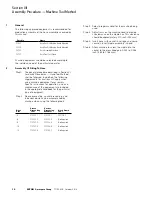
Step 1. Cut hose. Determine hose cut-off length
by subtracting cut-off factors from Table IV
from the desired hose assembly length.
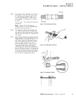
Cut hose squarely. A hose cut-off wheel
is recommended. To prevent a flare-out of
the wire end during the cut-off operation,
several layers of tape should be wrapped
around the hose at the cut-off point. After
the hose is cut, and before proceeding with
the assembly, the tape may be removed.
Caution:
Hold hose firmly against angle
plate or bolts of cut-off machine to bend
hose at cutting point. It is recommended
that the operator cut one sample and check
length before proceeding with cutting the
required quantity.
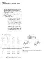
Figure 12. Cut-Off Factors
NOTE:
Cut-off factors are for one end only (see Figure 12). Add cut-off factors for
each end together and subtract from the desired hose assembly length to find the
correct hose cut length.
37º Flared Fittings
Size
Dim A
ST
Dim B
45º
Dim C
90º
-4
.92 (23.36)
2.06 (52.32
1.69 (42.92)
-6
1.04 (26.41)
2.35 (59.69)
1.92 (48.76)
-8
1.16 (29.46)
2.61 (66.29)
2.10 (53.33)
-10
1.21 (30.73)
2.74 (69.59)
2.06 (52.32)
-12
1.27 (32.25)
3.06 (77.72)
2.40 (60.95)
Flareless Fittings
Size
Dim A
ST
Dim B
45º
Dim C
90º
-4
1.69 (42.92)
2.79 (70.86)
1.69 (42.92)
-6
1.80 (45.72)
3.13 (79.50)
1.92 (48.76)
-8
2.14 (54.69)
3.55 (90.16)
2.10 (53.33)
-10
2.35 (59.69)
3.83 (97.28)
2.06 (52.32)
-12
3.70 (93.98)
4.38 (111.25)
2.40 (60.95)
Table IV Hose Cut-Off Factors
Dimensions shown in inches (mm)


