


Yellow symbol for
bypass mode
On
The UPS is in the bypass mode. The critical load
is supported by the bypass source. The green
indicator for normal operation is not illuminated
when the system is in the bypass mode.
Red symbol for active
alarm
On
The UPS has an active alarm and requires
immediate attention. The screen shows the
highest priority active alarms. All alarms are
accompanied by an audible horn. To silence the
horn, press any control panel button once. The
alarm indicator may be illuminated along with
other indicators.
7.2.2.1
UPS door color LED indicator
The LED indicators consist of two rows of LEDs located on the left and right sides
of the UPS cabinet door. The LEDs are red, green and yellow (RGY). The color of
the LED is used to indicate the condition of the UPS. The most urgent condition is
always the one shown. Only one color is shown at a time. The table below
defines which color is shown.
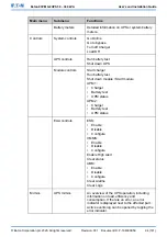
Table 26: Color LED indicators (screen and door)
Color LED
indicators (screen
and door)
UPS status
Normal operation
Battery mode
The green LEDs on the sides of the UPS cabinet door are
blinking and the yellow symbol for battery mode is illuminated
below the display. Since the battery mode is a normal condition of
the UPS, the green symbol for normal operation is also
illuminated below the display.
Bypass mode
Alarm
© Eaton Corporation plc 2020. All rights reserved.
Revision: 001
Document ID: P-164000956
91 (141)
Eaton 93PM G2 UPS 50 – 360 kVA
User’s and Installation Guide


