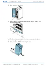
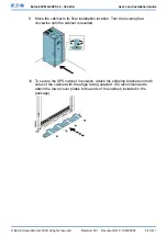


6.
Route and install the LAN and other cables to the appropriate MiniSlot cards.
The cable route is through the signal cable canal in the top section of the
UPS.
7.
For operator instructions, refer to the manual supplied with the MiniSlot card.
8.
When all the wiring is completed, close the front door and secure it with the
latch.
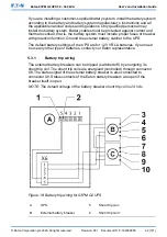
5.6.6
Install signal interface connections in a parallel system
Obey the instructions mentioned earlier when you install the signal interface
connections in a parallel system. Signal inputs can be paralleled between the
units, that is, the same contact can be used for several units’ signal input
signaling. This concerns also the EPO signal.
5.7
Wiring parallel 93PM G2 UPS systems
The outputs of multiple 93PM G2 UPS systems can be connected in parallel. Up
to 8units can be paralleled. The UPS static bypass power rating needs to be
identical among all the paralleled units. However, paralleled UPS cabinets can be
housed with different number of UPM power modules.
The outputs are paralleled to increase the load capacity of the power system and
for redundancy. The system is paralleled for (N+1) redundancy, as long as there
is always one or more UPS online than required to support the load. The system
is paralleled for capacity if all UPSs in a system are required to support the load.
Communication between the UPSs is required for system metering and mode
control. The system level communication and control are accomplished using a
Controller Area Network (CAN). A pull-chain signal in each UPS, connected to
the other UPSs in parallel and tied to the bypass status relay in each UPS, is
used for a secondary communication path. This arrangement ensures bypass
control even if the CAN bus is lost.
5.7.1
Power wiring overview
See
Section 5.8 UPS system power wiring preparations
for the recommended
cable and external fuse sizes and installation practices.
Input feed
The input feed is defined as the power source connected to the UPS rectifier. The
feed to all UPS’s inputs must be derived from the same source.
Bypass feed
The bypass feed is defined as the power source connected to the UPS bypass.
The feed to all UPS’s bypass must be derived from the same source. The
shortest length of power wire from the source to the UPS must be a minimum of
95% of the length of the longest wire.
© Eaton Corporation plc 2020. All rights reserved.
Revision: 001
Document ID: P-164000956
67 (141)
Eaton 93PM G2 UPS 50 – 360 kVA
User’s and Installation Guide


