


There is also one general alarm relay output on the front panel. This output is
either normally open (NO) or normally closed (NC). Polarity selection is made
with wiring connection. By default, the general alarm relay activates when a
system alarm is active, that is, any ALARM condition in the system is active.
Alternatively, it can be activated with any particular event but this must be
programmed separately by qualified service personnel. The alarm relay is
designed for signal level (ELV or SELV) voltages only, not for utility use. For
higher signaling circuit voltage requirements, please use Industrial Relay Adapter
in MiniSlot.
5.6.1
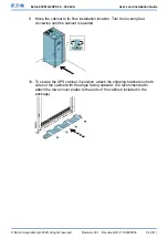
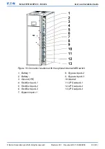
Install customer input signals interface
These inputs are located behind the UPS door, in the top section of the UPS. See
Figure 22: Communication interfaces
for the connector locations.
Tie points with strain relief for the communication cables are located on the right
and left side of the cable conduit.
Signal inputs can be configured to different functions. Normally these functions
are either informative (for example, “On Generator”) or functional (for example, a
remote “Go to bypass” command).
5.6.2
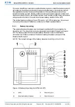
Battery breaker wiring interface
When the original accessory battery cabinet from the manufacturer is used, the
battery breaker interface wiring is provided with the cabinet. The wiring is
connected to the X8 terminal in the UPS.
When a third-party battery system is used, the breaker must be equipped with
auxiliary signal and should have a 24 Vdc shunt trip for remote opening of the
breaker, when needed.
See
Section 5.3.1 Battery trip wiring
for installation instructions.
5.6.3
Relay output interface connections
The general alarm relay is a dry relay signal output. The relay can be used for
informing the operators about UPS alarm conditions, for example through a
building management system. By default, the relay is configured to activate when
the UPS general alarm is active, that is, any event when the
ALARM
status is
active. The relay can also be configured to activate by some other event, but this
needs to be done by authorized service personnel.
Additional relay outputs are available with mini-slot cards. Relay outputs can be
configured to be activated by various events. Configuration can be done by an
authorized Eaton Customer Service Engineer or by other qualified service
personnel authorized by Eaton.
© Eaton Corporation plc 2020. All rights reserved.
Revision: 001
Document ID: P-164000956
65 (141)
Eaton 93PM G2 UPS 50 – 360 kVA
User’s and Installation Guide


