


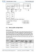

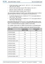

Figure 7: Path of current through the UPS in the battery mode
A
Static switch
1
Bypass input
Main power flow
B
Rectifier
2
Rectifier input
Energized
C
Inverter
3
Output
De-energized
D
DC/DC
converter
4
Battery breaker
Trickle current
E
Battery
Closed
Open
During a utility power failure, the rectifier no longer has an AC utility source from
which to supply the DC output current required to support the inverter. The input
relay K1 opens and the UPS output is powered from the batteries through the
inverter. As the inverter operates uninterrupted through the transition, the load
remains supported continuously without disturbance. If the UPS static bypass is
supplied from the same source as the UPS rectifier, the backfeed protection
contactor K5 also opens. The opening of K1 and K5 prevent system voltages
from bleeding backwards and re-entering the input source through the static
switch or rectifier.
© Eaton Corporation plc 2020. All rights reserved.
Revision: 001
Document ID: P-164000956
28 (141)
Eaton 93PM G2 UPS 50 – 360 kVA
User’s and Installation Guide


